Page 16 Installation and Safety Guidelines English
Installation pro.Bose.com
Configuration Changes Using Front Panel Controls
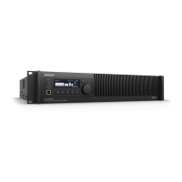
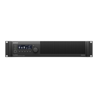
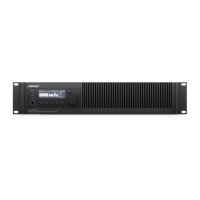
Navigation using the front-panel interface is intuitive with context-sensitive menus displayed above the soft-key buttons. Soft keys are
pressed to navigate to menu options. Data values are scrolled using the encoder knob, which is pressed to input a selected value. As an
example, the following steps outline how to change the default settings for several key functions.
Changing Default Output Attenuation
1. Starting from the default power up screen, press the MENU navigation key to access the MAIN MENU.
2. Press the LEVEL soft key.
3. Rotate the knob to highlight OUTPUT ATTENUATE then press the knob to navigate to the LEVEL<OUTPUT ATTEN screen.
4. Press the CHANNEL soft key and rotate encoder to highlight channel pairs for which change is desired.
5. Press CH (1 to 8) soft key to highlight current value of channel for which change is desired.
6. Rotate the knob to change the value of the highlighted channel in 0.5 dB increments and set to the desired value.
7. If change is desired for CH 2, press CH 2 soft key to highlight the current value. Turn knob to set the desired value.
8. If change in other channels is desired, Press the CHANNEL soft key and turn the knob to display desired channels.
Repeat 5 and 6.
9. If no additional change is required, press the BACK navigation key to return to the MAIN MENU <LEVEL screen.
10. Press the BACK navigation key to return to the MAIN MENU.
11. Press the BACK navigation key to return to the OPERATION screen.
12. Resume normal operation or make additional configuration changes using the menu.
Changing Output Configuration
1. Starting from the Operating Display, press the MENU navigation key to access the MAIN MENU.
2. Press the CONFIG soft key to access the CONFIGURE menu.
3. Rotate the knob to highlight Output Config and press knob to access CONFIG OUTPUTS menu.
4. Press CHANNEL soft key and rotate knob to display channel for which to change output configuration.
5. Press SELECT soft key and rotate knob to display desired output configuration.
6. Press knob to select desired configuration.
For changes to or from Mono, or any Voltage Bridge configurations, follow steps 7A to 10A. For changes to or from I-Share or Quad
Bridge configurations, follow steps 7B to 15B:
7A. Continue steps 4-6 until all output channel configurations have been changed to desired settings.
8A. Press BACK navigation key to return to CONFIGURE menu.
9A. Press BACK navigation key to return to MAIN menu.
10A. Press BACK navigation key to return to Operating Display.
For Change to or from I-Share or Quad Bridge Configurations:
7B. A warning message will be displayed to check output wiring. Make any required changes to output loudspeaker wiring and insert
shorting jumpers in output connectors as outlined on Page 14 in Figures 9 -11.
8B. Press CONFIRM soft key to set the configuration change.
Note: When changing to I-Share or Quad Bridge Modes, the amplifier will be placed in automatically in STANDBY Mode and will display
“IN STANDBY”
9B. Continue steps 4-6, then 7B-8B until all output channel configurations have been changed to desired settings.
10B. Press BACK navigation key to return to CONFIGURE menu.
11B. Press BACK navigation key to return to MAIN menu.
12B. Press UTILITY soft key to access Utility menu.
13B. Rotate knob to highlight Standby Mode and press knob to access Standby Menu.
14B. Press EXIT STANDBY soft key to enable the outputs and resume normal operation.
15B. Unit will automatically return to the Operating Display.
Note: When using ControlSpace Designer Software for setup and configuration, you may select if the front-panel controls are persistent
(they over-write any stored settings in the ControlSpace Design file), or if changes from the front panel are ignored after the next power
off/on cycle (the settings stored in the ControlSpace Design file over-write any front panel changes after power cycling). For additional
information, please refer to the ControlSpace Designer V3.0 User Manual.
All other front-panel interface menus use a similar navigation and data entry structure.
 Loading...

