27
Figure 15
Figure 16
Figure 17
Disassembly Procedures
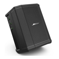
5. I/O Panel Removal
CAUTION: The integrated circuits used on the
S1 Pro
Main PCB are extremely sensitive to ESD
damage. Be sure to use an approved and tested
ESD strap that is properly grounded to your work
bench before attempting disassembly or repair of
the main PCB.
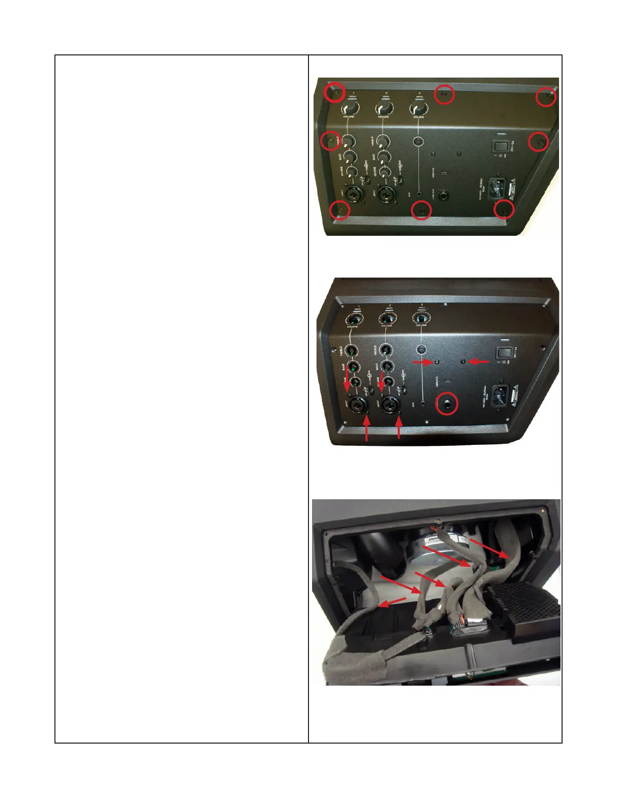
5.1 Red circles in gure 15 indicate #8 Torx
screws, remove these screws.
5.2 Remove the nine control knobs in gure 16.
5.3 Remove the screws indicated by the red
arrows and the nut and washer indicated by a red
circle in gure 16.
5.4 Lift out the I/O assembly as shown in gure
14.
Note: To avoid EMI issues, It is extremely
important to insure that the harnesses are placed
in the direction shown by arrows in gure 17
during reassembly.

 Loading...