29
Disassembly Procedures
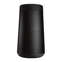
Figure 21
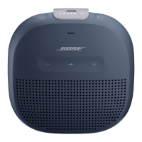
Figure 22
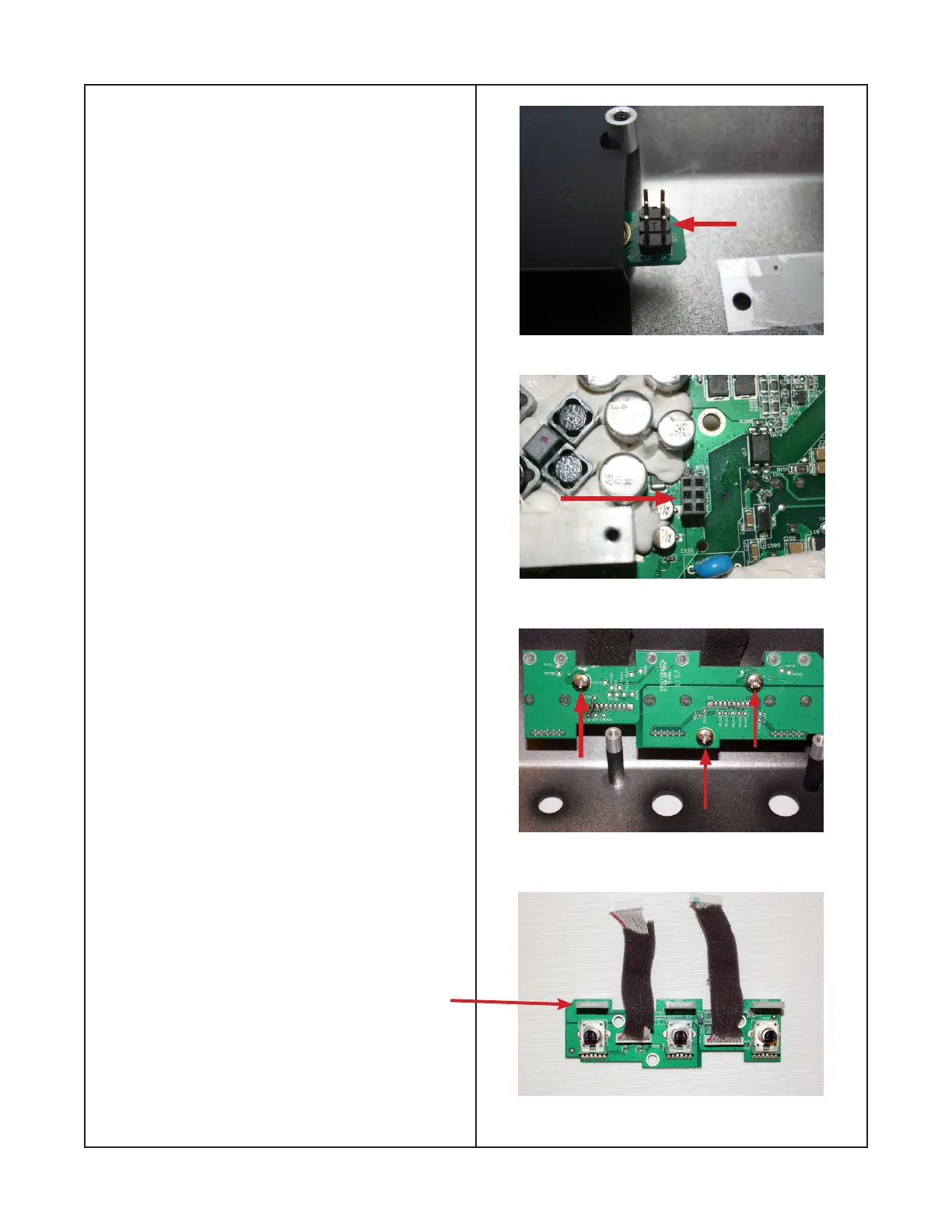
Figure 23
Figure 24
7.2 Figure 21 shows the power switch board
male connector as indicated by an arrow. Figure
22 shows the female connector on the main PCB
as indicated by an arrow.
Note: When reinstalling the main PCB assy,
insure that the two connectors are aligned.
8. Removing the Volume Control PCB
8.1 Perform procedures 5 thru 7.
8.2 Remove the three screws indicated by
arrows shown in gure 23.
8.3 Figure 24 shows the volume control board
assy and the two wire harnesses removed from
the I/O panel.
Note: When ordering a replacement Control
Board assy you must also order quantity of 3
789264-0010 Lightpipe. These will need to be
heat staked.

 Loading...