EasyManua.ls Logo

Boss AW-3 User Manual

Boss AW-3
9 pages
To Next Page IconTo Next Page
Page #1 background imageLoading...
Page #1 background image
AW-3 OCT. 2000
TABLE OF CONTENTS 目次
目次目次
目次 Page
SPECIFICATIONS .......................................................
主な仕様
................................................................................ 1
LOCATION OF CONTROLS ........................................
パネル配置図
....................................................................... 2
EXPLODED VIEW ......................................................
分解図
.................................................................................... 2
PARTS LIST.................................................................
パーツリスト
....................................................................... 3
TEST MODE ................................................................
テストモード
....................................................................... 5
CIRCUIT BOARD (CPU,LED,MAIN)............................
基板図(CPU,LED,MAIN)
.................................................. 8
CIRCUIT DIAGRAM (CPU,LED,MAIN)........................
回路図(CPU,LED,MAIN)
.................................................. 9
17059063 Printed in Japan A000 (CM)
SPECIFICATIONS/
• AW-3:Dynamic Wah
Nominal Input Level
-20 dBu
Input Impedance
1 M ohm
Nominal Output Level
-20 dBu
Output Impedance
1 k ohm
Recommended Load
Impedance
10 k ohm or greater
Residual Noise
-92 dBu (IHF-A Typ.)
Controls
Pedal Switch
DECAY Knob
MANUAL/VOWEL 2 Knob
SENS/VOWEL 1 Knob
MODE Switch
Indicator
CHECK Indicator (Serves also
as tempo and battery check
indicator)
Connectors
GUITAR IN Jack
BASS IN Jack
OUTPUT Jack
EXP/CTL Jack
AC adaptor Jack
Power Supply
DC 9 V:
Dry battery (9 V type)
S-006P/9 V (6F22/9 V)
Dry battery (9 V type)
6AM6/9 V (alkaline)
AC Adaptor
(PSA-series: optional)
Current Draw
50 mA (DC 9 V)
* Expected battery life under
continuous use:
Carbon: 2 hours
Alkaline: 6 hours
These figures will vary depend-
ing on the actual conditions of
use.
Dimensions
70 (W) x 125 (D) x 55 (H) mm
2-13/16 (W) x 4-15/16 (D) x 2-
3/16 (H) inches
Weights
420 g /15 oz (including Battery)
Accessories
Owner's Manual
English(#G6017286)
Japanese(#G6017285)
Dry battery (9 V type) S-006P/9
V (6F22/9 V)(#********)
* The battery that was supplied
with the unit is for temporary
use-intended primarily for test-
ing its operation.
We recommend that alkaline
batteries be used when replac-
ing the batteries.
Options
AC Adaptor (PSA-series)
Expression pedal Roland EV-5
Footswitch (momentary-type)
BOSS FS-5U
Dry battery (9 V type) 6AM6/9
V (alkaline)
* 0 dBu = 0.775 Vrms
* In the interest of product
improvement, the specifications
and/or appearance of this unit
are subject to change without
prior notice.
主な仕様
主な仕様主な仕様
主な仕様
AW‑3:ダイナミック・ワウ
AW‑3:ダイナミック・ワウ AW‑3:ダイナミック・ワウ
AW‑3:ダイナミック・ワウ
規定入力レベル
規定入力レベル規定入力レベル
規定入力レベル
‑20dBu
入力インピーダンス
入力インピーダンス入力インピーダンス
入力インピーダンス
1MΩ
規定出力レベル
規定出力レベル規定出力レベル
規定出力レベル
‑20dBu
出力インピーダンス
出力インピーダンス出力インピーダンス
出力インピーダンス
1kΩ
推奨負荷インピーダン
推奨負荷インピーダン推奨負荷インピーダン
推奨負荷インピーダン
10kΩ 以上
残留ノイズ
残留ノイズ残留ノイズ
残留ノイズ
‑92dBu(IHF‑ATyp.)
コントロール
コントロールコントロール
コントロール
ペダル・スイッチ
DECAY つまみ
MANUAL/VOWEL2 つまみ
SENS/VOWEL1 つまみ
MODE スイッチ
インジケーター
インジケーターインジケーター
インジケーター
CHECK インジケーター(テン
ポ、バッテリー・チェック兼
用)
接続端子
接続端子接続端子
接続端子
GUITARIN ジャック
BASSIN ジャック
OUTPUT ジャック
EXP/CTL ジャック
AC アダプター・ジャッ
電源
電源電源
電源
DC9V:
乾電池(9V)S‑006P/9V
(6F22/9V)
乾電池(9V)6AM6/9V
(アルカリ)
AC アダプター
消費電流
消費電流消費電流
消費電流
50mA(DC9V)
連続使用時の電池の寿命
(使用状態によって異なりま
す)
マンガン電池約 2 時間
アルカリ電池約 6 時間
外形寸法
外形寸法外形寸法
外形寸法
70(幅)× 125(奥行)× 55
(高さ)mm
質量
質量質量
質量
420g(乾電池含む)
付属品
付属品付属品
付属品
取扱説明書
和文:(#G6017285)
英文:(#G6017286)
愛用者カード (#********)
乾電池(9V)S‑006P/9V
(6F22/9V):(#********)
付属の乾電池は動作確認用
です。電池の寿命は前記時
間より短くなる場合があり
ます。また、交換時にはア
ルカリ乾電池を推奨します。
別売品
別売品別売品
別売品
AC アダプター(PSA‑100)
エクスプレッション・ペダル
RolandEV‑5
フット・スイッチ(モーメン
タリー・タイプ)BOSSFS‑5U
(推奨)乾電池(9V)6AM6/9V
(アルカリ)
0dBu=0.775Vrms
製品の仕様および外観は、
改良のため予告なく変更す
ることがあります。
製品やアフター・サービス
に関するお問い合わせは、
付属の『サービスの窓口』
をご覧ください。
Question and Answer IconNeed help?

Do you have a question about the Boss AW-3 and is the answer not in the manual?

Boss AW-3 Specifications

General IconGeneral
TypeAuto Wah
Input Impedance1 M ohm
Output Impedance1 k ohm
ControlsMode, Depth, Level
Power Supply9V DC
Inputs1 x 1/4" (Input)
Outputs1 x 1/4" (Output)
Dimensions73 mm (W) x 129 mm (D) x 59 mm (H)

Summary

AW-3 Specifications

Input/Output Specifications

Details input/output levels, impedance, and load impedance.

Performance Specifications

Details residual noise and current draw.

Controls and Indicators

Lists control elements, pedal switch, and CHECK indicator.

Connectors and Power

Lists connectors and describes power supply requirements.

Physical Characteristics

Provides the physical dimensions and weight of the unit.

Accessories and Options

Included Manuals

Lists the owner's manuals provided with the unit.

Optional Items

Lists optional accessories that can be purchased separately.

Location of Controls

Front Panel Layout

Identifies controls on the front panel, including pots and switches.

Pedal Mechanism

Identifies the main pedal and its associated base.

Exploded View Components

External Parts

Lists case, screws, washers, cushion, spring, and other external parts.

Internal and Mounting Parts

Lists battery connector, binding machine, insulation spacer, and covers.

Parts List Overview

Safety Precautions

Lists safety precautions for parts replacement.

Electronic Components

Lists transistors, diodes, resistors, potentiometers, capacitors, inductors, crystals.

Hardware and Assemblies

Lists knobs, buttons, switches, jacks, sockets, and PWB assemblies.

Integrated Circuits (ICs)

Lists integrated circuit components used in the unit.

Wiring and Cable Identification

Flat Cable

Identifies the flat cable component.

Hardware and Fasteners

Screws, Nuts, and Washers

Identifies various screws, nuts, spacers, and washers.

Specialized Fasteners

Identifies items like binding tapping and internal teeth.

Miscellaneous Parts

Electrical and Structural Parts

Lists battery connectors, springs, cushions, terminals, posts, and ties.

Standard Accessories

Power and Documentation

Lists dry battery and owner's manuals.

Test Mode Operations

Test Item List

Lists the specific items to be tested in test mode.

Required Test Equipment

Lists the necessary equipment for performing tests.

Entering and Exiting Test Mode

Instructions on how to enter and exit the test mode.

Basic Component Checks

Details checks for DSP, CPU, DECAY, MANUAL, and SENS controls.

Pedal Functionality Tests

Details procedures for testing the EXP PEDAL and CTL PEDAL.

Test Mode Operations

Switch and CODEC (DAC) Tests

Describes tests for FET switch and CODEC (DAC) L/R channels.

Noise Level Testing

Describes procedures for checking residual and shock noise levels.

Test Mode Operations

CODEC (ADC) Channel Tests

Details checks for CODEC (ADC) R and L channels.

Selective Test Execution

Explains how to perform specific tests by skipping others.

Circuit Board Layouts

Main PWB Assembly Layout

Shows the physical layout of the main PWB assembly.

VR Board Layout

Shows the physical layout of the VR board.

Circuit Diagrams

Main PWB Circuit Diagram

Provides the detailed circuit diagram for the main PWB assembly.

VR Board Circuit Diagram

Provides the detailed circuit diagram for the VR board.
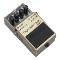
Related product manuals