7 Detecting and correcting faults
900-301_IFU-V2.2_11316-S0-20131023-EN Operating Manual ARC 250 / 303 51
7. Detecting and correcting faults
Two types of faults can occur:
system faults
EASY monitoring faults
7.1. System errors
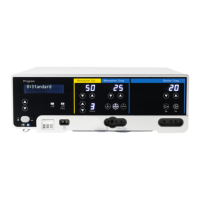
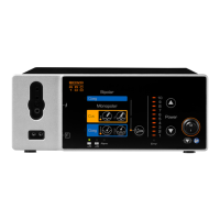
When a system error occurs, the error indicator 18 lights up red. "INF"
appears on the "Monopolar Cut" display 2, and a one- to three-digit error
code appears on the "Monopolar Coag" display 9.
Pos: 61 /679-BOW A/HF-Geräte/ ARC 300/350/7 F ehler/UE_Fehler- Liste - Titel @ 6\mod_1297 678255465_6. doc @ 48513 @ 3
7.1.1. Error list
Pos: 62 /679-BOW A/HF-Geräte/ ARC 200/250/3 00e/7 Fehler/Fehl er-Liste @ 6\ mod_12971473 33340_6.doc @ 48258 @ 2
Errors not listed
Contact the service center in case of errors not shown in the error
list, see section Technical service, page 59.
If the expected change in the tissue does not occur and no error
message appears, check the parameters and the accessory
connections.
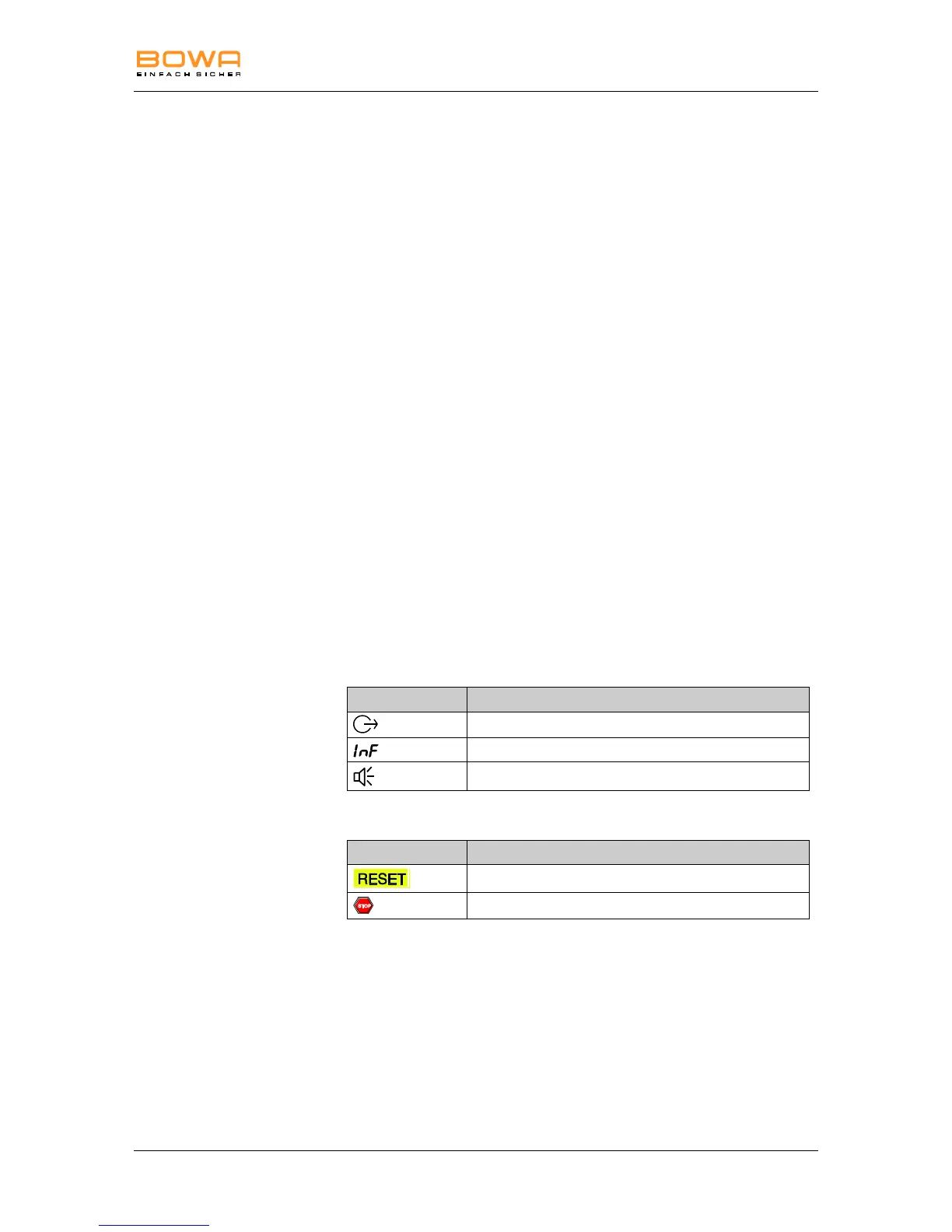
Visual and acoustic signals indicating errors
The error messages are accompanied by visual and acoustic signals.
Furthermore, the generator cancels activation if certain errors occur and
the system is reset.
Optical and acoustic signals:
Contact the service center if the suggested corrective measure
does not eliminate the error, see section Technical service,
page 59.