41
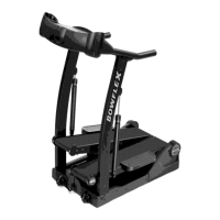
Printed Circuit
Board Assembly
(PCBA)
Printed Circuit
Board Assembly
(PCBA)
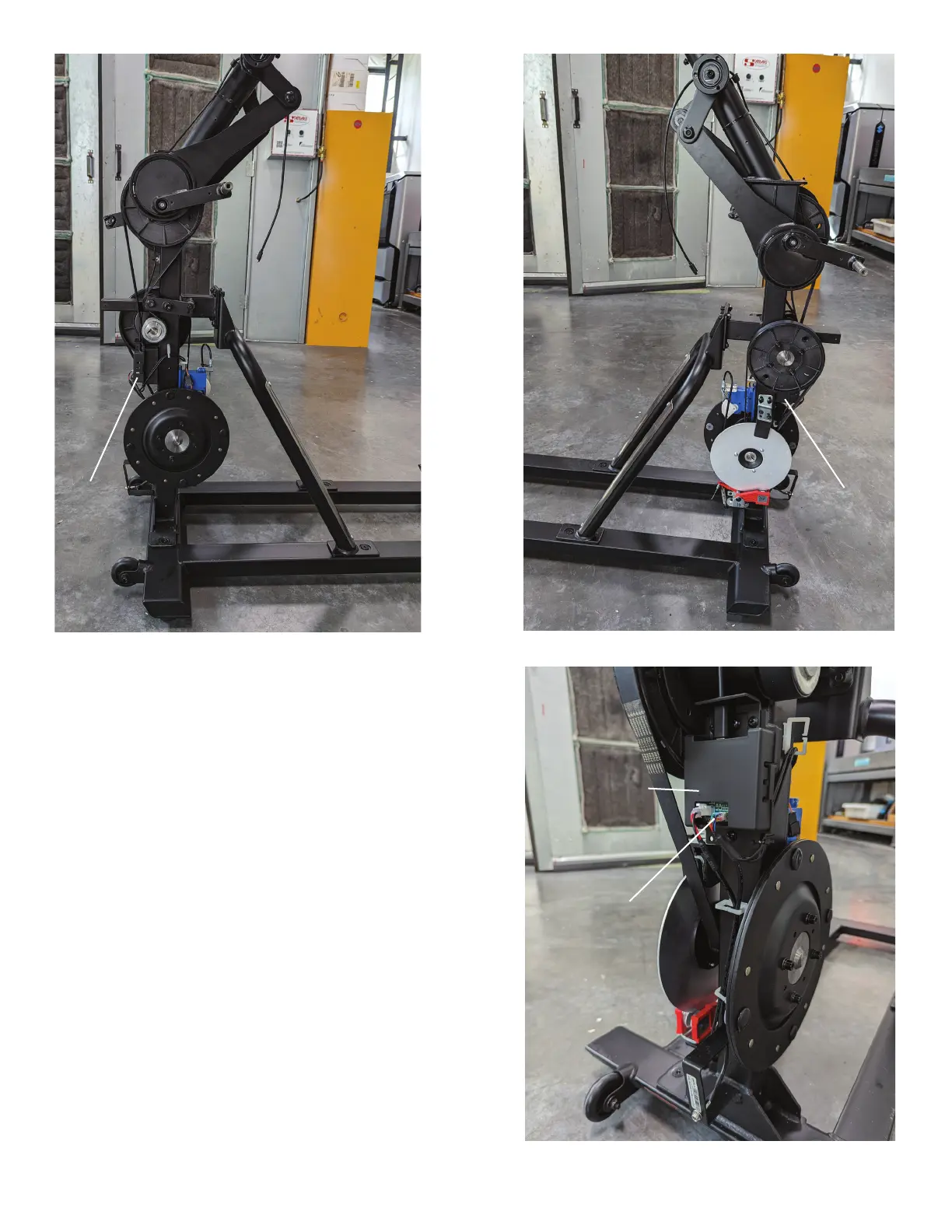
19. Remove the Split Cable from the PCBA.
Note: Be sure to note where all cables attach for re-
assembly. If the Cable Connector is secured by a small
amount of glue, use a pair of small nose pliers to grab
and remove the glue.
NOTICE: Do not cut or pinch the cables.
20. The Split Cable routes to the Servo Motor, Speed
Sensor, and the Resistance Sensor. Disconnect
the old Split Cable from the PCBA, and connect
the new Split Cable to the PCBA. This will make
it easier to route the dierent arms of the Split
Cable along the old path.
Printed Circuit
Board Assembly
(PCBA)
Split Cable
(Servo, Speed
and Resistance)
Assembly