32
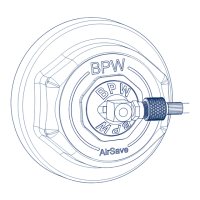
Fig. 43
ISO 7638
ISO 1185
(24 N)
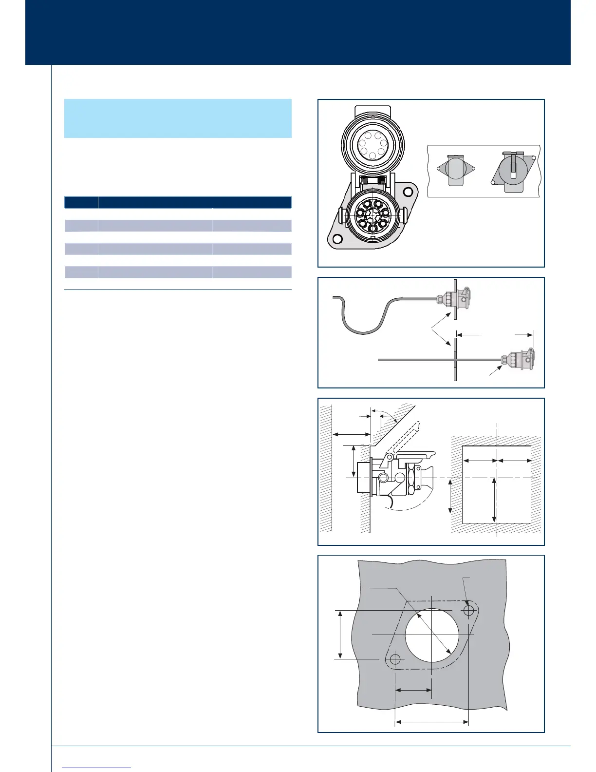
Fig. 44
Gland nut
Trailer
headboard
approx.
350 mm
3 Chassis installation
3.2 Electrical wiring
ISO 7638 Connector
Should be positioned/grouped with other electrical connections
(Fig. 43).
Pin detail and identifi cation key location.
When installing ISO 7638 it is important that suffi cient extra
length of cable is allowed to expose the socket assembly for
replacement in service (Fig. 43).
It will be necessary to pull the ISO 7638 socket clear from the
trailer headboard to undo the gland nut (Fig. 44).
Clearance dimensions (Fig. 45).
Socket mounting dimensions (Fig. 46).
Pin No. Designation
1 Red (RD) 4 mm
2
Plus electro valve
2 Black (BK) 1.5 mm
2
Plus electronics
3 Yellow (YE) 1.5 mm
2
Minus electronics
4 Brown (BN) 4 mm
2
Minus electro valve
5 White (W) 1.5 mm
2
Warning device
6 White/Green (W/GN) 1.5 mm
2
CAN H
7 White/Brown (W/BN) 1.5 mm
2
CAN L
Fig. 46
50.3 mm
48.7 mm
25.15 mm
24.25 mm
74.9 mm
74.3 mm
37.45 mm
37.15 mm
Ø 9 mm
Ø 8.5 mm
Ø 57 mm
Ø 55 mm
Fig. 45
max.
10 mm
45º
max. 60 mm
min.
55 mm
min. min.
60 mm 60 mm
min.
80 mm
2
1
3
4
5
6
7
3.2.5 General installation recom-
mendations - ISO 7638
min.
120 mm
 Loading...