41
3.2 Electrical wiring
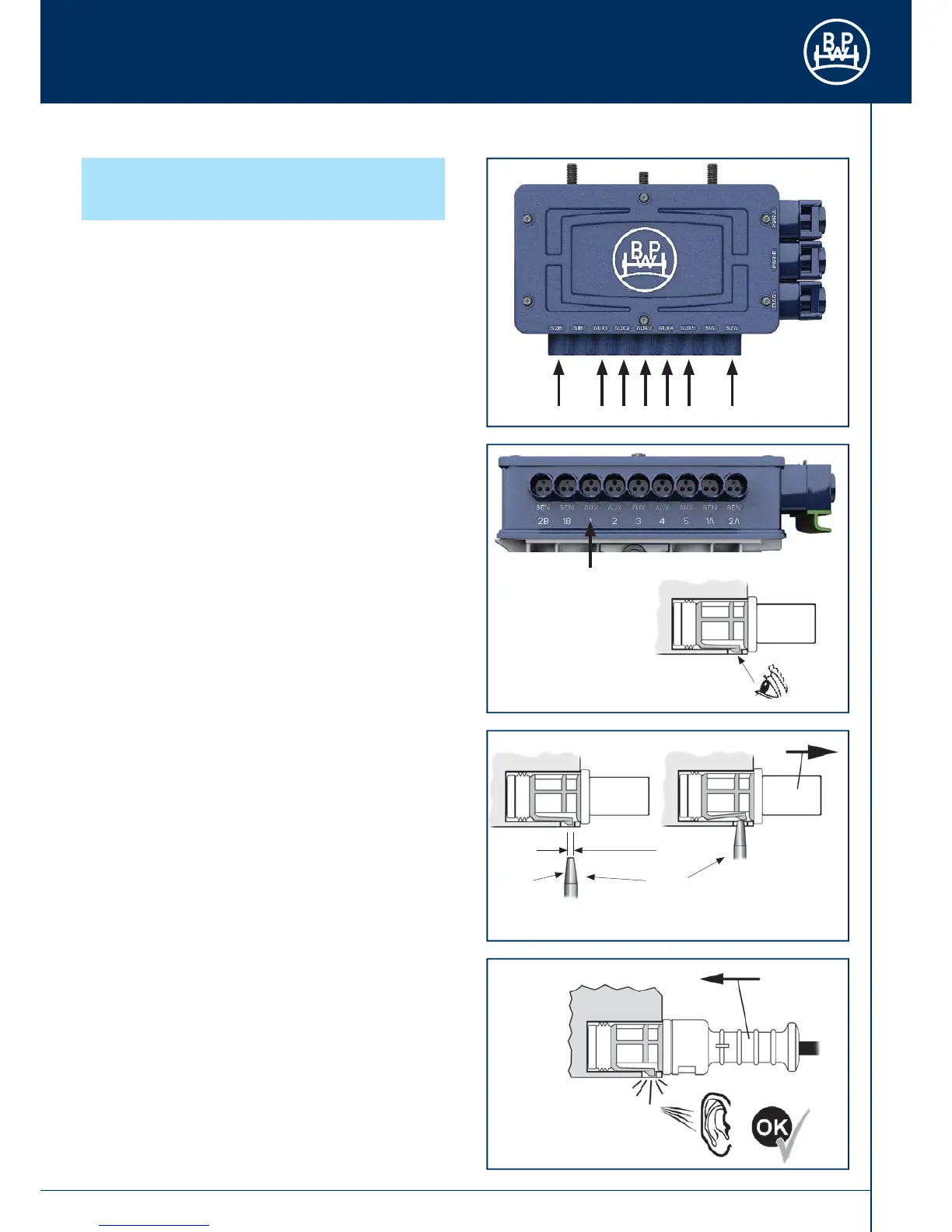
The ECU is supplied with blanking plugs in positions indicated
(Fig. 68). These require to be removed to allow fi tment of
additional sensors or permitted ancillary equipment.
Example - „AUX 1” connection
Identify the „AUX 1” position on the top or front face of the ECU.
Note the locking tag position (Fig. 69/arrow).
With a tool having a fl at end of Ø 2 - 3 mm insert and press in
locking tab of plug. While depressed pull out plug from housing
(Fig. 70).
Identify orientation of the:
• Sensor black body connector
• Auxiliary blue body connector
Ensure contact pins and seal are kept clean and free of any
contamination prior to installation. Insert fully home in the ECU’s
housing into appropriate marked positions (Fig. 71).
Fig. 68
Fig. 69
Fig. 70
Fig. 71
ECU
P
ECU
ECU
Ø 2 - 3 mm
3.2.14 Sensor /
AUX connections
Tool
 Loading...