40
3 Chassis installation
3.2 Electrical wiring
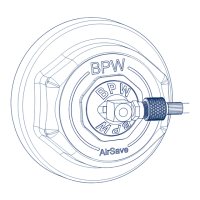
Sensor Plug
Identification tags are incorporated on either side of the
sensor / ECU connector (Fig. 66).
These must be removed to identify the appropriate sensor
before connecting into the ECU (Fig. 66).
ECU Identifi cation Tags Removed
1 2 3 4 A B P 5
Component
S1A Sensor 1A
S1B Sensor 1B
S2A Sensor 2A
S2B Sensor 2B
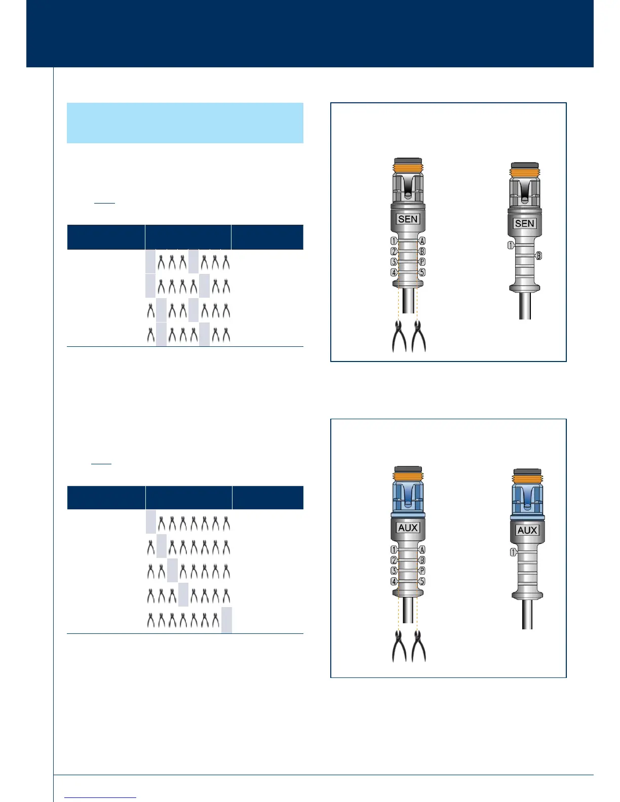
Auxilliary Plug
Identifi cation tags are incorporated on either side of the Auxilliary
connector (Fig. 67).
These must be removed to identify the appropriate usage before
connecting into the ECU (Fig. 67).
ECU Identifi cation Tags Removed
1 2 3 4 A B P 5
Component
Example only
AUX 1 COLAS
®
+
AUX 2 ILAS
®
-E
AUX 3 Warning lamp
AUX 4 LWS
AUX 5 TRS
Fig. 66
Fig. 67
BLACK
front case
}
}
BLUE
front case
Example: COLAS
®
+
Example: Sensor 1B
3.2.13 Sensor / AUX plugs
 Loading...