65
5.2 Air suspension
Application
The levelling valve is installed as a level control valve for load
depended control using the air bellows of vehicles with air
suspension. Depending on the version, additional functions,
such as 2. drive height, through a lap position control are
possible.
Principle of operation
Air spring valves are secured on the vehicle frame and are
connected to the axle with the round or fl at lever via leverage.
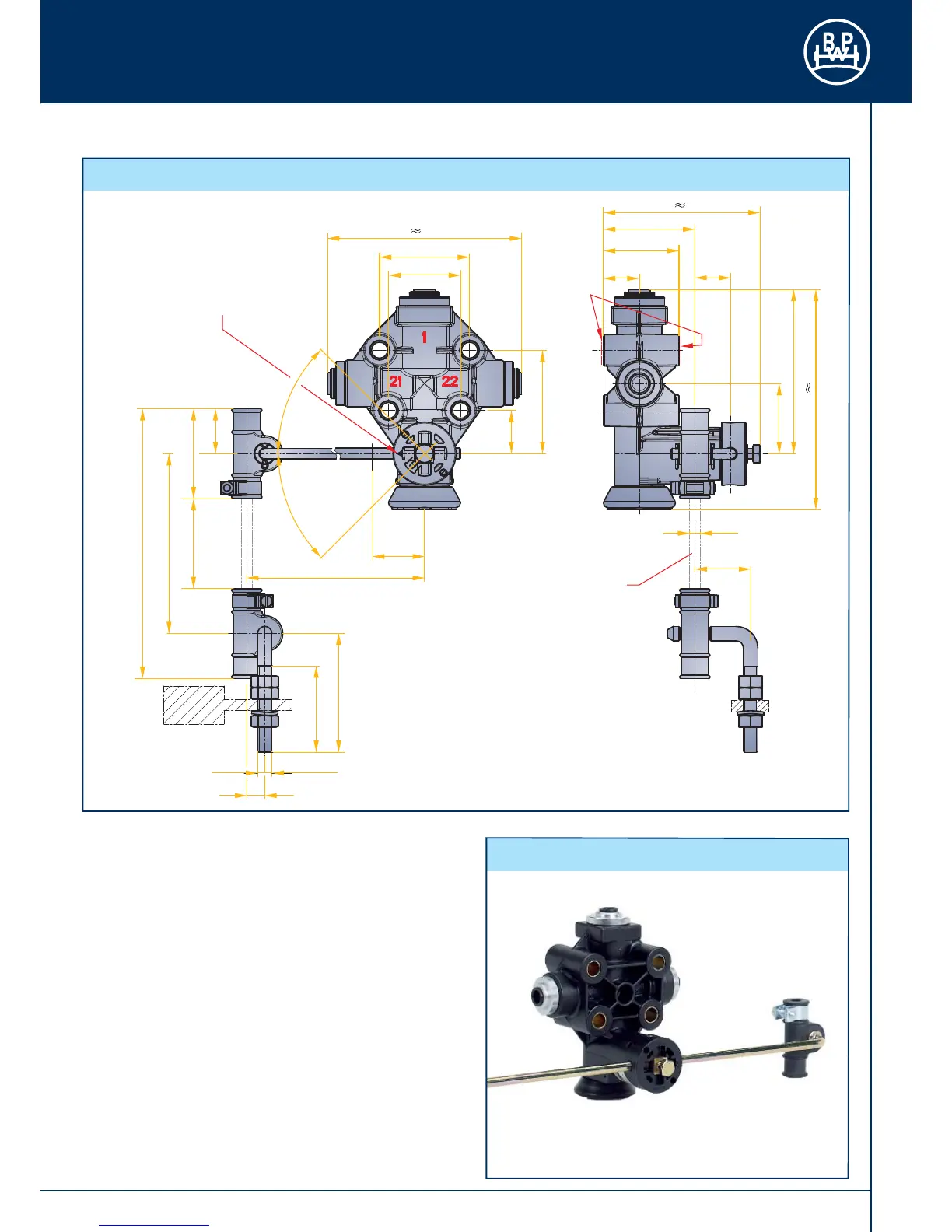
The pneumatic connections are made via a reserve connector
(1), two energy outfl ows (21 and 22), as well as via the vent (3).
When in the resting state, the valve is said to be in the so-called
fi nishing position, i.e. both infl ow and also outfl ow are closed.
Fig. 115
5.2.1 Standard air spring valve – dimensions and connections
31
Ø 6
39
91
122
87
51
42
20
20
10
M8
48
66
X+100
min. 60
X
50
25
24
57,5
max. 320
110
50
40
min. 80
Discharging
Charging
45°
45°
Identification mark for the
lever mounting position,
lever swivel angle 360°
Linkage assembled
without tension (valve axle)
Washer DIN 125B
Tightening torque: 22 24 Nm
3
 Loading...