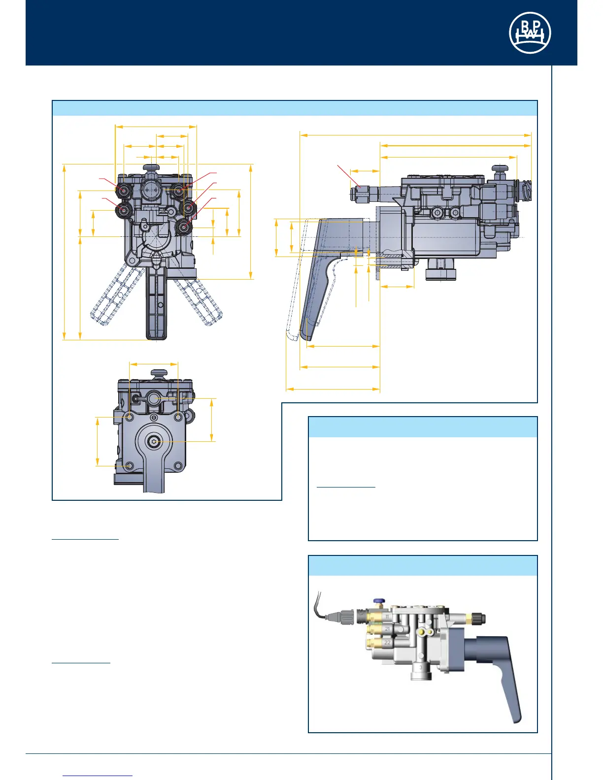
73
Installation Guidelines
Mechanical Part:
Attachment is by at least 2 holes provided on the housing with
M 8 bolts and a tightening torque of 15 Nm (13.5 - 16.5 Nm).
The installation site must be chosen so that the COLAS
®
+ valve
is protected from spray or high pressure wash water. Good
accessibility to the operating lever must be provided. Ensure that
the unit does not protrude outside the overall vehicle width. The
vehicle manufacturer must provide suitable protection against
unauthorised activation.
Electrical Part:
Bayonet connection according to DIN 72585. For the bayonet
connection, turn the union nut clockwise to make certain that
it is correctly attached and locks in to ensure optimum sealing.
An electrical connection to the solenoid valve is permissible only
via the ECO Tronic EBS-ECU, which provides a signal „Reset
to ride height“. BPW Bergische Achsen is not liable for other
types of actuation.
Operating pressure: p
e
max. 8.5 bar
Operating temperature: - 40° C to +80°C
Weight: approx. 1.5 kg
Solenoid Valve:
perm. duty cycle 10 s
Voltage U
B
= 24 VDC +7/-8
Current / Output lo= 250 mA / Po = 6 W
Protection class DIN 40050 - IP 6K 9K
Fig. 130
Fig. 129
Technical Data
Electrical Connection
5.2 Air suspension
5.2.4 COLAS
®
+
 Loading...