Do you have a question about the BRADEN CH SERIES and is the answer not in the manual?
Locates the model and serial number on the winch for reference.
Details the meaning of each part of the winch model number for identification.
Essential safety guidelines for operating and servicing the winch.
Defines the meaning of WARNING and CAUTION emblems used in the manual.
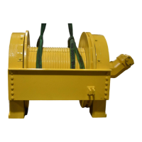
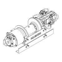
Details the main sub-assemblies that constitute the hoist unit.
Explains the mechanical principles behind the hoist's planetary gearing.
Describes the components and function of the dual brake system.
Explains the operational sequence of the dual brake system during hoisting and lowering.
Outlines general requirements for mounting and connecting the hoist.
Details the correct method for installing wire rope onto the winch drum.
Lists part numbers for wire rope wedges based on rope diameter.
Illustrates the hydraulic circuit for single-speed hoists.
Illustrates the hydraulic circuit for two-speed hoists.
Instructions for checking the gear oil level and frequency.
Details the required frequency and importance of changing gear oil.
Guidance on maintaining the vent plug and hydraulic system filter.
Recommends inspecting wire rope according to manufacturer guidelines.
Specifies mounting bolt torque checks and essential warm-up procedures.
Details the recommended gear oils based on ambient temperature.
Highlights importance of immediate troubleshooting for erratic operation.
Addresses issues with pilot orifice, brake cylinder seal, or brake discs.
Diagnoses oil leaks from the vent plug, relating to motor seals or back pressure.
Covers causes like back pressure, worn brake discs, or slipping brake clutch.
Addresses mounting distortion, binding, or incorrect relief valve settings.
Continues diagnosis of hoisting problems, including hydraulic temperature.
Investigates causes of winch overheating, such as heat exchangers or oil levels.
Addresses winching 'chatter' related to hydraulic flow or control operation.
Diagnoses problems with wire rope not spooling smoothly on the drum.
Details initial steps for draining oil and removing motor and tie plates.
Covers removal of brake cylinder, motor adapter, and planetary gears.
Details removal of drum closure, ring gear adapter, and thrust bearings.
Covers removing output planet carrier, drum, and checking bearing support.
Step-by-step instructions for disassembling the brake cylinder.
Advises caution regarding compression tool use to prevent damage.
Details lubricating and installing O-rings, backup rings, and springs.
Covers installing retaining ring, piston plate, and performing pressure checks.
Instructions for removing pins, gears, bearings, and inspecting for wear.
Details installing bearings, thrust washers, gears, and securing with pins.
Recommends using safe solvents for cleaning hoist components.
Guides inspection for wear, damage, and proper function of parts.
Instructions for removing snap ring, retainer, inner race, and sprag clutch.
Warns about the importance of smooth surfaces for clutch engagement.
Details pressing bushings, installing clutch parts, and securing snap rings.
Covers cleaning, lubricating, installing bearings, seals, and planet carriers.
Details installing output sun gear, planet carriers, and ring gear adapter.
Covers installing brake cylinder, clutch assembly, discs, and checking stack-up height.
Details installing motor end plate, brake cylinder nipple, tie plates, and hydraulic hoses.
Covers engaging the motor, installing hoses, and final system checks.
Illustrates typical motor installations for understanding rotation reversal.
Details initial steps for motor removal and brake clutch inspection.
Covers re-installing the brake clutch, motor, and performing system checks.
General advice on servicing brake valves and importance of cleanliness.
Lists components for the 1 1/4 inch brake valve with part quantities.
Lists components for the 1 1/2 inch brake valve with part quantities.
Details disassembly steps for pilot orifice, drain check ball, and spool assembly.
Instructions for cleaning, inspecting O-rings, springs, and valve bores.
Step-by-step guide for reassembling the brake valve components.
Conversions for linear measurements, area, and volume.
Conversions for mass, pressure, power, torque, velocity, and temperature.
| Gear Ratio | Varies by model |
|---|---|
| Weight | Varies by model |
| Motor Type | Hydraulic |
| Drum Diameter | Varies by model |
| Drum Length | Varies by model |
| Wire Rope Capacity | Varies with drum size |