Factory Setting
Switch Default Options Comments
5
NOTES - Heat Pump Systems
[1]Ifbatteriesareinstalledthe24VoltACcommonconnectionisoptional.
[2]SelectOforcoolactiveor Bforheatactive.
[3]InstallaeldsuppliedjumperbetweentheW2 and Eterminalsif
thereisnoseparateemergencyheatrelayinstalled.
Provide disconnect and overload protection as required.
CONV/HP CONV
F/C F
HE/HG HG
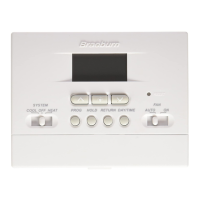
Set Installer Switches
4
CONV Selectforconventionalsystems
HP Selectforheatpumpsystems
F Selectforfahrenheittemperaturescale
C Selectforcelsiustemperaturescale
HG Selectforgasheat
HE Selectforelectricheat
Typical Wiring Configurations
NOTE: The “Installer Switch” option will be configured in the next step.
Heat Pump Systems
1 HEAT / 1 COOL - No Auxiliary Heat
Set Installer Switch to HP
Rh 24VoltACPower
Rc ConnectedtoRhwithsuppliedJumperWire
O or B
ChangeoverValve [note 2]
Y1 CompressorRelay
G FanRelay
C 24VoltACTransformerCommon [note 1]
2 HEAT / 1 COOL - Including Auxiliary Heat (2220NC only)
Set Installer Switch to HP
Rh 24VoltACPower
Rc ConnectedtoRhwithsuppliedJumperWire
O or B
ChangeoverValve[note 2]
Y1
CompressorRelay(1ststageheating/cooling)
W2 AuxiliaryHeatRelay(2ndstageheating)
[note 3]
E EmergencyHeatRelay[note 3]
G FanRelay
C 24VoltACTransformerCommon [note1]
TheInstallerswitchesarelocatedonthebackofthethermostatandmust
beproperlyconguredforthisthermostattooperateproperly.

 Loading...