Thermostat Location
Installthethermostatapproximately5feet(1.5m)abovetheoorinanareathathasagoodamountofair
circulationandmaintainsanaverageroomtemperature.
Avoidinstallationinlocationswherethethermostatcanbeaffectedbydrafts,deadairspots,hotorcoldair
ducts,sunlight,appliances,concealedpipes,chimneysandoutsidewalls.
Installer Guide 2
3 Installer Guide
Install your new Braeburn thermostat in 4 basic steps:
1 InstalltheSub-Base
2 ProvidePower
3 ConnectYourWires
4 AttachThermostattoSub-Base
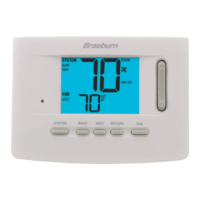
Install the Sub-Base:
•Removethesub-basefromthebodyofthethermostat.
•Mountthesub-baseasshownbelow:
Warning
Disconnect power before beginning installation.
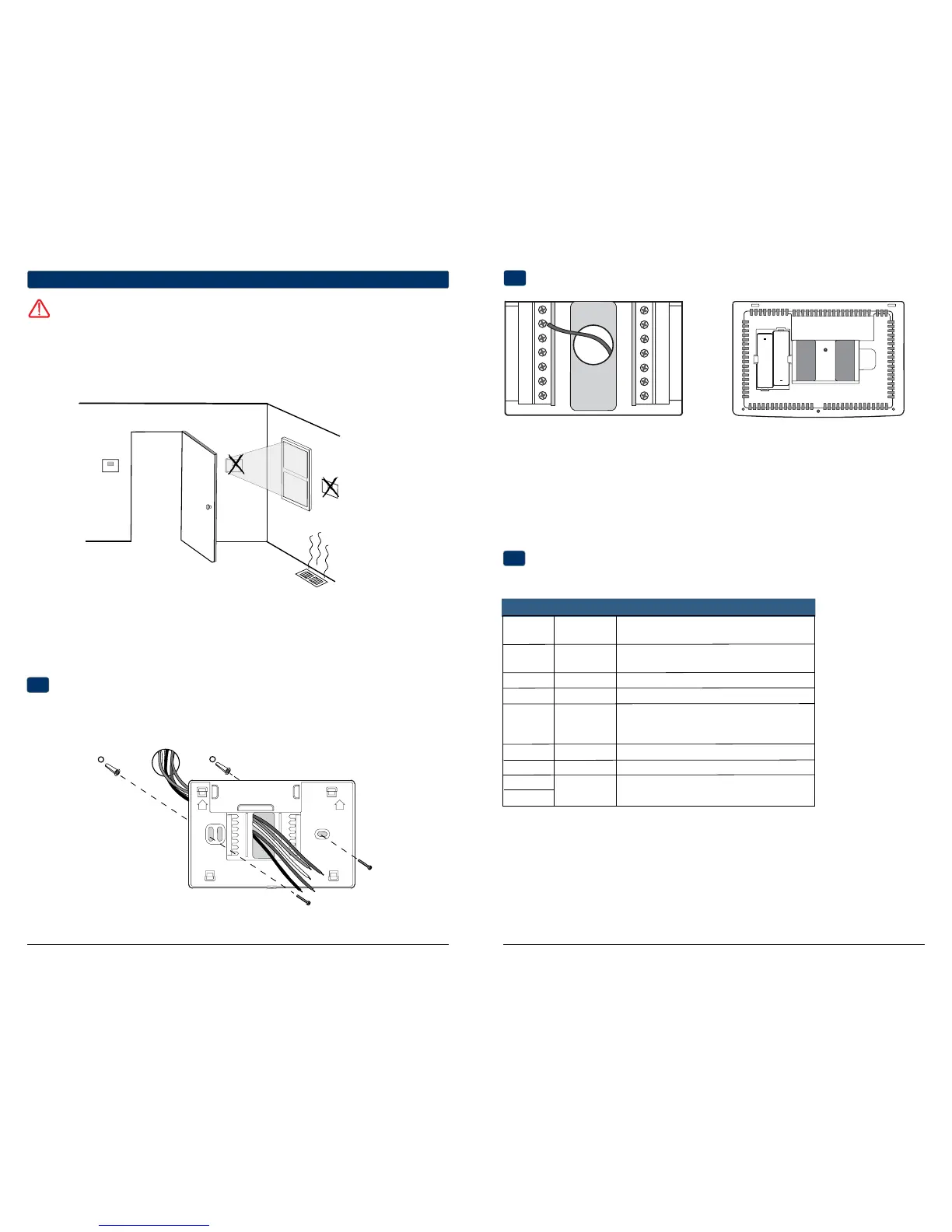
Provide Power
C
24VAC Power Terminal (C)
2
Installation and Wiring
1
2
Wiring Terminations for model 3020
Terminal Function Description
Rc Input 24VoltACCoolingTransformer
(DualTransformerSystemsOnly)
Rh Input PowerConnection(24VoltACHeating
TransformerorMillivoltPowerSource)
G Output FanControl
W1 Output ConventionalHeatRelay
O/B/V3 Output (O)CoolActiveReversingValve
(B)HeatActiveReversingValve
(V3)ZoneValvePowerClose
Y1 Output CompressorRelay
C Input 24VoltACTransformerCommon
S1
S2
Connect Your Wires
3
Input OptionalRemoteSensor(indoororoutdoor)
UP
UP
Drill 3/16” pilot holes in your
desired location. Use supplied
anchors for drywall or plaster.
+
+
• For24VoltACpower,youmustconnectthecommonsideofthetransformertotheCterminalonthethermostatsub-base.In
dualtransformerinstallations,thetransformercommonmustcomefromthecoolingtransformer.
• Forbatterypower,insertthe2supplied“AA”typealkalinebatteriesintothebatterycompartmentlocatedintherear
housingofthethermostat.MakesuretopositionthePositive(+)andNegative(-)sidesofthebatteriescorrectlywith
the+/-symbolsinthebatterycompartment.
Batteries Installed as Shown
 Loading...