Installer Guide 4
5 Installer Guide
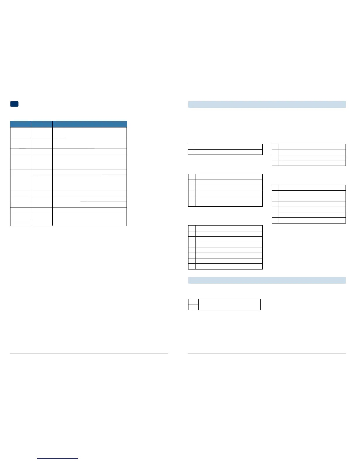
Wiring Terminations for model 3220
Terminal Function Description
Rc Input 24VoltACCoolingTransformer
(DualTransformerSystemsOnly)
Rh Input PowerConnection(24VoltACHeating
TransformerorMillivoltPowerSource)
G Output FanControl
W1/E/W3 Output (W1)1stStageConventionalHeat,
(E)EmergencyHeat,
(W3)3rdStageAuxiliaryHeat
W2 Output 2ndStageConventionalHeat
O/B/V3 Output (O)CoolActiveReversingValve
(B)HeatActiveReversingValve
(V3)ZoneValvePowerClose
Y1 Output 1stStageCompressor
Y2 Output 2ndStageCompressor
L Input SystemMalfunctionIndicator
C Input 24VoltACTransformerCommon
S1
S2
Heat Only or Millivolt
Set System Type to 11CONV
Rh PowerConnection
W1 HeatRelay
Connecting Your Wires (continued)
1 HEAT / 1 COOL Single or Dual Transformer
Set System Type to 11CONV
Rh
24VoltACPower(heatingtransformer)[note 2]
Rc
24VoltACPower(coolingtransformer)[note 2]
W1 HeatRelay
Y1 CompressorRelay
G FanRelay
C 24VoltACTransformerCommon[note 1, 3]
NOTES - Conventional Systems
[1]Optional24VoltACcommonconnection.
[2]Removefactoryinstalledjumperfordual
transformersystems.
[3]Indualtransformersystems,transformer
commonmustcomefromcoolingtransformer.
[4]ConnectY2onlyifasecondcoolingcompressor
isbeingused.
Provide disconnect and overload protection as required.
2 HEAT / 2 COOL Single or Dual transformer
Set System Type to 22CONV
Rh
24VoltACPower(heatingtransformer)[note 2]
Rc
24VoltACPower(coolingtransformer)[note 2]
W1 HeatRelayStage1
W2 HeatRelayStage2
Y1 CompressorRelayStage1
Y2 CompressorRelayStage2 [note 4]
G FanRelay
C 24VoltACTransformerCommon[note 1, 3]
3
Input OptionalRemoteSensor(indoororoutdoor)
Typical Wiring Congurations
NOTE: The “System Type” option will be configured in the Installer Settings section. The 3020 is a single stage
thermostat and not intended for multi stage equipment.
Conventional Systems
NOTE: Additional options are configured in the
Installer Settings section.
S1
S2
NOTES - Additional Wiring Options
[1]Theseterminalscanbeusedtoconnecta
Braeburn
®
indoororoutdoorremotesensor.
Additional Wiring Options
IndoororOutdoorRemoteSensor[note 1]
Hydronic Heat Only
Set System Type to 1HD
Rh
24VoltACPower(heatingtransformer)
W1 ZoneValvePowerOpen
V3 ZoneValvePowerClose
C 24VoltACTransformerCommon[note 1]
Hydronic Heat / 1 Cool
Set System Type to 11HD
Rh
24VoltACPower(heatingtransformer)[note 2]
Rc
24VoltACPower(coolingtransformer)[note 2]
W1 ZoneValvePowerOpen
V3 ZoneValvePowerClose
Y1 CompressorRelay
G FanRelay(coolingfanonly)
C 24VoltACTransformerCommon[note 1, 3]
 Loading...