INSTRUCTIONS
TheInstallerSettingsmustbeproperlyconguredinorderforthisthermostattooperatecorrectly.TheInstaller
Settingsaremenudriven.Theportionofthesesettingsthatdonotapplytoyoursetupwillbeskipped.These
settingsareindicatedbelowwithcomments.Moredetailoneachsettingfollowsthistable.
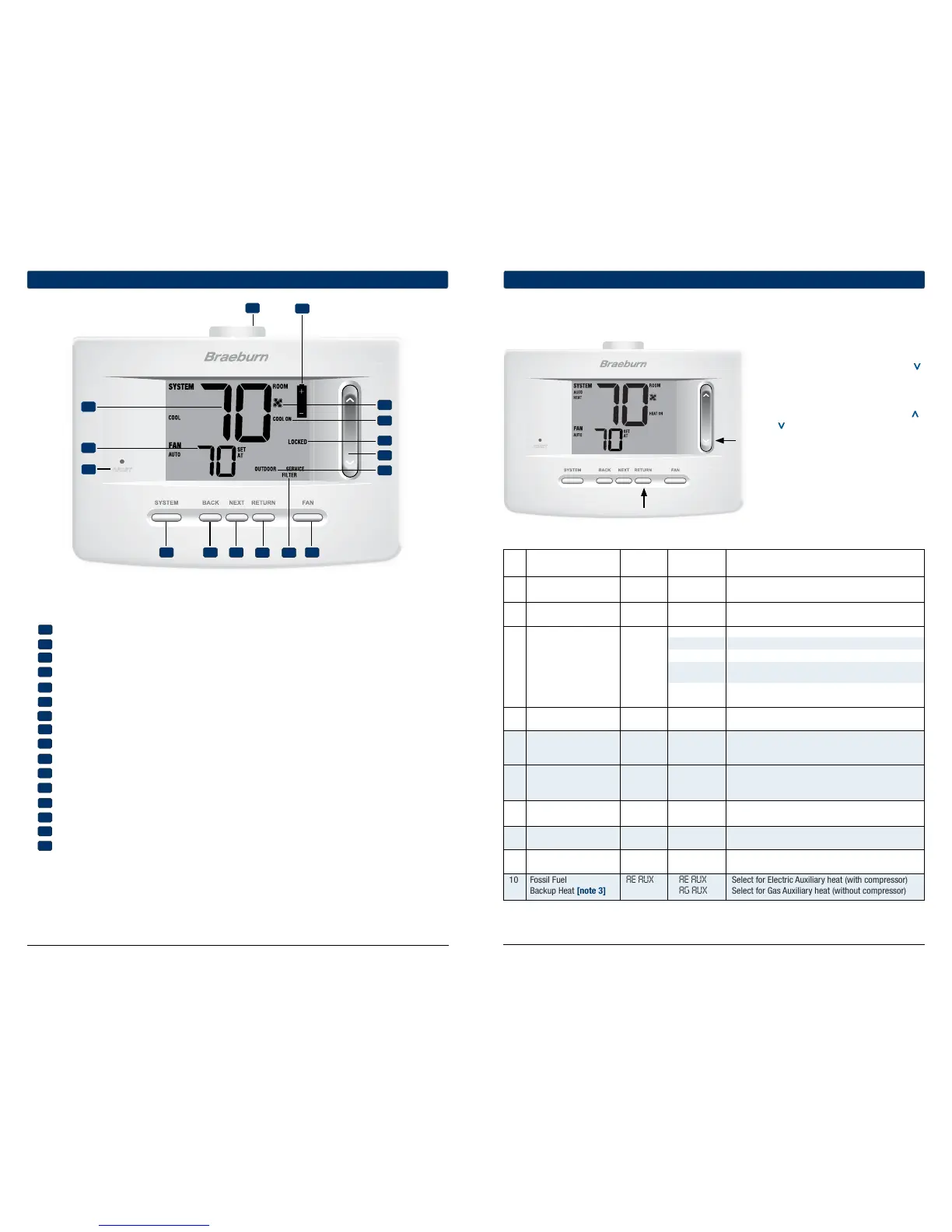
1. PressandholddowntheRETURNand
buttonsfor3seconds.
2. Releasebothbuttonsandtherstinstaller
settingwillbedisplayed.
3. Changesettingsasrequiredusingthe
orportionoftheSpeedBar
®
.
4. PressNEXTorBACKtomovetothenext
orprevioussetting,pressRETURNtoexit.
No. Installer Setting Factory Setting Comments
(
Notes follow this table) Default Options (More information follows this table)
1 TemperatureScale F DEG F DEG SelectforFahrenheitdisplay
C DEG SelectforCelsiusdisplay
2 AutoChangeover oF AUTO oF AUTO DisablesAutoChangeovermode
ON AUTO EnablesAutoChangeovermode
11CONV Selectfor1H/1CConventionalsystem
22CONV Selectfor2H/2CConventionalsystem
3 SystemType 11CONV 11HP Selectfor1H/1CHeatPumpsystem
22HP Selectfor2H/2CHeatPumpsystem
32HP Selectfor3H/2CHeatPumpsystem
1HD SelectforHeatOnlyHydronicsystem
11HD SelectforHydronicHeat/1Csystem
4 1stStageDifferential 0.5 DIF1 0.5, 1.0or Selecta1ststagetemperaturedifferentialof.5°,
2.0 DIF1 1°or2°F(0.2°,0.5°or1°C)
5 2ndStageDifferential 2.0 DIF2 1.0, 2.0, 3.0, Selecta2ndstagetemperaturedifferentialof1°,
[note 1] 4.0, 5.0or 2°,3°,4°,5°or6°F(0.5°,1°,1.5°,2°,2.5°or3°C)
6.0 DIF2
6 3rdStageDifferential 2.0 DIF3 1.0, 2.0, 3.0, Selecta3rdstagetemperaturedifferentialof1°,2°,
[note 1] 4.0, 5.0or
3°,4°,5°or6°F(0.5°,1°,1.5°,2°,2.5°or3°C)
6.0 DIF3
7 1stStageFanControl HG FAN 1 HG FAN 1 Selectfor1ststageGasheating
[note 2] HE FAN 1 Selectfor1ststageElectricheating
8 EmergencyHeat] HE EMER HE EMER SelectforElectricEmergencyHeat
FanControl[note 3] HG EMER SelectforGasEmergencyHeat
9 ReversingValve REVO REVO SelectforcoolactiveReversingValve(Oterminal)
(O/BTerminal)[note 4] REVB SelectforheatactiveReversingValve(Bterminal)
10 FossilFuel AE AUX AE AUX SelectforElectricAuxiliaryheat(withcompressor)
BackupHeat[note 3] AG AUX SelectforGasAuxiliaryheat(withoutcompressor)
4
Installer Settings
9 Installer Guide
Installer Guide 8
INSTRUCTIONS
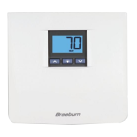
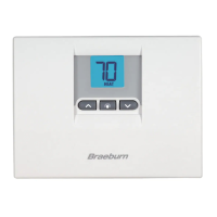
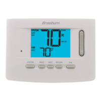
Room Temperature...................... Displaysthecurrentroomtemperature
Set Temperature.......................... Displaysthecurrentsetpointtemperature
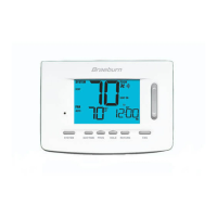
Reset Button ............................... Resetscurrenttime,programandusersettings
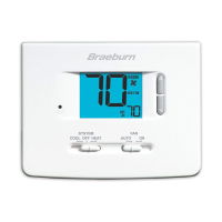
SYSTEM Button............................ Selectsthesystemyouwanttocontrol
BACK Button.................................Movesbackininstaller/usersetupmodes
NEXT Button................................. Movesforwardininstaller/usersetupmodes
RETURN Button............................ Returnstonormalmodefrominstaller/usersetupmodes
Service Indicators ...................... Displaysvariousservice/maintenanceinformation
FAN Button...................................Selectsthesystemfanmode
Quick Reference Instructions...... Storedinslotlocatedattopofthermostat
Low Battery Indicator.................. Indicateswhenthebatteriesneedtobereplaced
Fan Indicator................................ Indicateswhenthesystemfanisrunning
System Status Indicator ............. Displaysinformationaboutthestatusofthesystem
Lock Mode Indicator ................... Indicatesifthethermostatislocked
SpeedBar
®
................................... Increasesordecreasessettings(time,temperature,etc.)
Outdoor Temperature Indicator....
Displaysalongwiththeoutdoortemperaturereading(seenotebelow)
Installer Clear Button .................. Locatedonbackofthermostatbody–clearsallsettings
Battery Compartment ................. Locatedinthebackofthermostat
3
Quick Reference
1
2
3
5
15
7
14
16
13
12
11
10
1
2
3
4
5
6
7
8
9
10
11
Thermostat and Display
12
13
14
6
8
4 9
15
16
NOTE: If a Braeburn
®
outdoor sensor was connected you can view the outdoor temperature by
pressing the BACK and NEXT buttons at the same time.
NOTE: Shaded areas below do not apply to the 3020.
 Loading...