INSTRUCTIONS
Installer Guide 6
7 Installer Guide
NOTE: This thermostat ships congured as a 1H/1C conventional
thermostat. Conrm installer settings. See page 9.
UP
UP
1 HEAT / 1 COOL - No Auxiliary Heat
Set System Type to 11HP
Rh 24VoltACPower
Rc ConnectedtoRhwithsuppliedJumperWire
O/B
ChangeoverValve [note 2]
Y1 CompressorRelay
G FanRelay
C 24VoltACTransformerCommon [note 1]
3 HEAT / 2 COOL – Including Auxiliary Heat
Set System Type to 32HP
Rh 24VoltACPower
Rc
ConnectedtoRhwithsuppliedJumperWire
O/B ChangeoverValve [note 2]
Y1
Compressor1Relay(1ststageheating/cooling)
Y2
Compressor2Relay(2ndstageheating/cooling)
W3
AuxiliaryHeatRelay(3rdstageheating)[note 5]
G FanRelay
C 24VoltACTransformerCommon[note 1]
L OptionalSystemFaultMonitor[note 4]
2 HEAT / 1 COOL - Including Auxiliary Heat
Set System Type to 22HP
Rh 24VoltACPower
Rc ConnectedtoRhwithsuppliedJumperWire
O/B
ChangeoverValve[note 2]
Y1 CompressorRelay(1ststageheating/cooling)
W2
AuxiliaryHeatRelay(2ndstageheating)[note 3]
E EmergencyHeatRelay[note 3]
G FanRelay
C 24VoltACTransformerCommon[note 1]
L OptionalSystemFaultMonitor[note 4]
2 HEAT / 2 COOL - No Auxiliary Heat
Set System Type to 32HP
Rh 24VoltACPower
Rc ConnectedtoRhwithsuppliedJumperWire
O/B
ChangeoverValve[note 2]
Y1
Compressor1Relay(1ststageheating/cooling)
Y2
Compressor2Relay(2ndstageheating/cooling)
G FanRelay
C 24VoltACTransformerCommon[note 1]
L OptionalSystemFaultMonitor[note 4]
NOTES - Heat Pump Systems
[1] Optional24VoltACcommonconnection.
[2] O(coolactive)orB(heatactive)isselectedin
theInstallerSettingsmenu.
[3] Installaeldsuppliedjumperbetweenthe
W2andW1/E/W3terminalsifthereis
noseparateemergencyheatrelayinstalled.
4
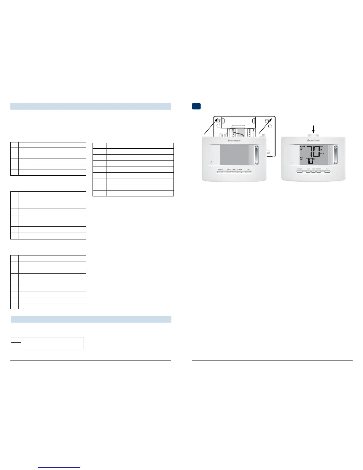
Attach Thermostat to Sub-Base
[4] IftheLterminalisused,the24VoltACcommon
mustbeconnected(Cterminal).
[5] Ifaseparateemergencyheatrelayisinstalled,the
W1/E/W3terminalshouldhaveboththeauxiliary
heat1relayandemergencyheatrelayconnected.
Provide disconnect and overload protection as required.
3) InsertQuickReferenceCardintoslot
ontopofthermostat.
1) Lineupthethermostatbodywiththesub-base.
2) Carefullypushthethermostatbodyagainstthe
sub-baseuntilitsnapsinplace.
Typical Wiring Congurations
NOTE: The “System Type” option will be configured in the Installer Settings section. The 3020 is a single
stage thermostat and not intended for multi stage equipment.
Heat Pump Systems
NOTE: Additional options are configured in the
Installer Settings section.
S1
S2
NOTES - Additional Wiring Options
[1]Theseterminalscanbeusedtoconnecta
Braeburn
®
indoororoutdoorremotesensor.
Additional Wiring Options
IndoororOutdoorRemoteSensor[note 1]
 Loading...