5 Installer Guide
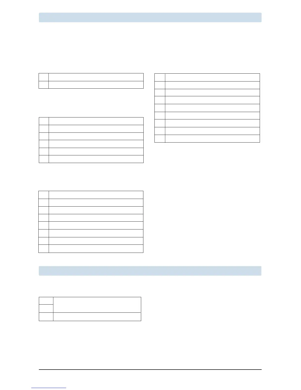
Heat Only or Millivolt
Set System Type to 11CONV
Rh PowerConnection
W1 HeatRelay
1 HEAT / 1 COOL Single or Dual Transformer
Set System Type to 11CONV
Rh
24VoltACPower(heatingtransformer)[note 2]
Rc
24VoltACPower(coolingtransformer)[note 2]
W1 HeatRelay
Y1 CompressorRelay
G FanRelay
C 24VoltACTransformerCommon[note 1, 3]
NOTES - Conventional Systems
[1]Optional24VoltACcommonconnection.
[2]Removefactoryinstalledjumperfordual
transformersystems.Providedisconnectand
overloadprotectionasrequired.
[3]Indualtransformersystems,transformer
commonmustcomefromcoolingtransformer.
[4]ConnectY2onlyifasecondcoolingcompressor
isbeingused.
Provide disconnect and overload protection as required.
3 HEAT / 2 COOL Single or Dual Transformer
Set System Type to 32CONV
Rh
24VoltACPower(heatingtransformer)[note 2]
Rc
24VoltACPower(coolingtransformer)[note 2]
W1 HeatRelayStage1
W2 HeatRelayStage2
W3 HeatRelayStage3
Y1 CompressorRelayStage1
Y2 CompressorRelayStage2 [note 4]
G FanRelay
C 24VoltACTransformerCommon[note 1, 3]
2 HEAT / 2 COOL Single or Dual transformer
Set System Type to 22CONV
Rh
24VoltACPower(heatingtransformer)[note 2]
Rc
24VoltACPower(coolingtransformer)[note 2]
W1 HeatRelayStage1
W2 HeatRelayStage2
Y1 CompressorRelayStage1
Y2 CompressorRelayStage2 [note 4]
G FanRelay
C 24VoltACTransformerCommon[note 1, 3]
Typical Wiring Configurations
NOTE: The “System Type” option will be configured in the Installer Settings section. The 5310 is a single stage
thermostat and not intended for multi stage equipment.
Conventional Systems
NOTE: Additional options are configured in the
Installer Settings section.
S1
S2
A EconomizerControl(5320only)[note 2]
NOTES - Additional Wiring Options
[1]Theseterminalscanbeusedtoconnecta
Braeburn
®
indoororoutdoorremotesensor.
[2]
Thisterminalcanbeusedforeconomizer
control(5320).
Additional Wiring Options
IndoororOutdoorRemoteSensor[note 1]

 Loading...