3 Installer Guide
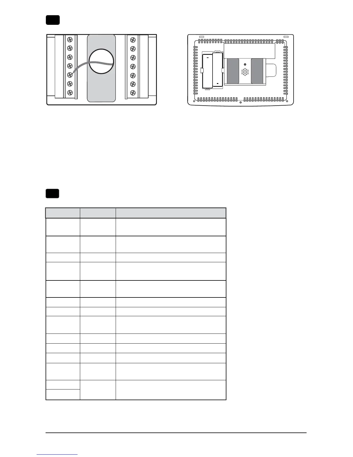
Provide Power
C
24VAC Power Terminal (C)
2
Connect Your Wires
3
+
+
• For24VoltACpower,youmustconnectthecommonsideofthetransformertotheCterminalonthethermostat
sub-base.Indualtransformerinstallations,thetransformercommonmustcomefromthecoolingtransformer.
• Forbatterypower,insertthe2supplied“AA”typealkalinebatteriesintothebatterycompartmentlocatedintherear
housingofthethermostat.MakesuretopositionthePositive(+)andNegative(-)sidesofthebatteriescorrectlywith
the+/-symbolsinthebatterycompartment.
• IfconnectingthisthermostattoaWi-Finetwork,a24VACcommon(Cwire)isrequired.
Batteries Installed as Shown
Terminal Function Description
Rc Input 24VoltACCoolingTransformer
(DualTransformerSystemsOnly)
Rh Input PowerConnection(24VoltAC
HeatingTransformer)
C Input 24VoltACTransformerCommon
W2/AUX Output (W2)2ndStageConventionalHeat
(AUX)AuxiliaryHeat(HeatPump)
W1/E Output (W1)1stStageConventionalHeat
(E)EmergencyHeat
L Input SystemMalfunctionIndicator
A Output Economizer,FreshAirorOutputControl
O/B Output (O)CoolActiveReversingValve
(B)HeatActiveReversingValve
G Output FanControl
Y2 Output 2ndStageCompressor
Y1 Output 1stStageCompressor
K - OptionalShare-a-Wire
TM
moduleconnection
S2
S1
Input OptionalWiredRemoteSensor
(indoororoutdoor)

 Loading...