Do you have a question about the Brain Bee 9000 Bus Plus and is the answer not in the manual?
General notes and copyright information regarding the reproduction and use of the manual.
General operating instructions, safety warnings, and intended use of the equipment.
Details about the manufacturer, Brain Bee S.p.A., including contact information.
Defines the warranty terms, conditions, period, and exclusions for the equipment.
Information on authorized service centers and how to obtain assistance for repairs.
Details about the equipment's CE marking, conformity, and the importance of the data plate.
Defines terms like dangerous areas and operators, outlining operator duties and responsibilities.
Lists prohibited operations, fuse usage, electrical connection safety, and precautions during servicing.
Explains the safety devices present in the 9000 BUS PLUS, such as pressure switches and safety valves.
Instructions on how to use the manual, its importance, and copyright information.
Explains various safety and warning symbols used throughout the manual and on the equipment.
Defines key technical terms used in the manual for better comprehension.
Provides precautions for storing and handling refrigerant, including safety sheets and conditions.
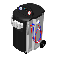
Identifies external components of the 9000 BUS PLUS from the front view.
Identifies internal components visible from the front view.
Identifies external components of the 9000 BUS PLUS from the rear view.
Identifies internal components visible from the rear view.
Identifies components visible from the right side of the 9000 BUS PLUS.
Identifies components visible from the left side of the 9000 BUS PLUS.
Identifies gauges and display from the front side view.
Details the operation and navigation of the touchscreen interface.
Explains the indicators shown on the status bar, such as vessel pressure and refrigerant amount.
Describes the purpose and operation of various function keys on the equipment.
Explains the patented ECO LOCK® couplers and their benefits.
Lists the basic set of accessories included with the equipment.
Lists optional accessories available for purchase, such as leak test kits and cleaning kits.
Covers the initial setup and installation process for the 9000 BUS PLUS unit, including unpacking and preparation.
Step-by-step instructions for safely unpacking the equipment from its pallet and packaging, noting two operators are required.
Guidelines for connecting the unit to the electric mains and A/C system.
Instructions on proper unit placement, ventilation, and electrical grounding.
Procedure for the initial filling of the internal refrigerant tank.
Steps for filling the new oil bottle with appropriate lubricant.
Steps for filling the tracer bottle with fluorescent pigment for leak detection.
Configures various parameters including Hybrid Function, Eco Lock, Recharge Mode, Pressure Check, Air Purge, Multipass, Reports, Hoses Length, Unit of Measure, Clock, Garage Data, Language, and Drive Type.
Notes on optimal conditions for refrigerant recovery and recharge, and features of new couplers.
Explains the AIR PURGE SYSTEM function for detecting and removing non-condensable gases.
Describes the two different refrigerant recharge modes available on the unit.
General procedure for performing automatic A/C system service, including connection requirements.
Accessing the database for vehicle selection and performing automatic cycles for buses.
Accessing the database for vehicle selection and performing automatic cycles for other vehicles.
Utilizes the Autodata database for selecting vehicle A/C system data to speed up operations.
Loads the parameters from the last performed automatic cycle.
Allows loading previously saved automatic cycle parameters defined by the user.
Details how to configure parameters like refrigerant amount, oil injection, oil type, and UV injection for automatic cycles.
Explains how to set and replace the oil type used in the A/C system service.
Requirements for connecting LP and HP couplers to the vehicle A/C system before manual operations.
Procedure for recovering refrigerant from the vehicle A/C system using manual mode.
Steps for performing the vacuum phase and the subsequent vacuum test.
Process for injecting refrigerant and oil into the A/C system using manual controls.
Instructions for performing system flushing with optional accessories to purify the A/C circuit.
Procedure for checking the vehicle A/C system pressures after connecting the equipment.
Instructions to completely empty the recharge hoses after use.
Describes the nitrogen leak test for checking A/C system tightness using an optional kit.
Performing an internal leak test of the CLIMA tool components and circuits.
Function to determine and store the atmospheric pressure value for calibration.
Details the LONG LIFE PUMP special function for optimizing vacuum pump oil life and replacement.
General instructions for replacing dryer filters to maintain system efficiency.
Specific steps and equipment required for changing the dryer filter.
Notification system for when dryer filters are nearing their replacement limit.
Accessing information on pump and compressor operating hours and filter replacement intervals.
Procedure for filling the internal vessel with refrigerant, including safety warnings.
Checking and manually discharging non-condensable gases from the tank.
Activating the multipass function for enhanced refrigerant recycling and service quality.
Displaying identifying codes and software versions of the 9000 BUS PLUS station.
Instructions for changing the paper roll in the integrated thermal printer.
Requirements and frequencies for periodic requalification and checks of the equipment and its components.
Procedures for disposing of the A/C service unit at the end of its service life.
Guidelines for consigning recovered refrigerant and lubricants to appropriate collection centers.
Instructions for disposing of packaging materials in accordance with local environmental regulations.
| Brand | Brain Bee |
|---|---|
| Model | 9000 Bus Plus |
| Category | Service Equipment |
| Language | English |