3
Installation Procedure
1. Identify installation location. MEGAbite piping should originate shortly after incoming
water supply shutoff, but just after any outside water lines, such that all water intended for
interior use flows through MEGAbite first. IMPORTANT: there must not be any filters in-
stalled upstream of the MEGAbite, or insufficient water pressures may affect operational
performance. This system and installation must comply with state and local laws and regu-
lations. This system is to be supplied only with cold water.
2. Connect water piping. This unit has been supplied with a manually operated bypass device
which enables it to be isolated from the water service lines for maintenance and service, and
also maintain the continuity of the water supply when the MEGAbite is disconnected.
IMPORTANT: Make all sweat-solder connections within 6 inches of the unit before apply-
ing threaded fittings to supplied bypass valve. Overheating may cause damage to valve.
Turn supplied bypass valve to “Bypass” position and make connections to household water
lines. Leave unit in “Bypass” position until startup procedure.
3. Connect drain line. Remove barbed or push-to-connect drain line fitting from parts bag.
Apply thread seal tape to threads and turn into the female threaded opening on the back side
of the control valve. Connect 5/8” drain line (supplied in parts bag) to barbed or push-to-
connect end of drain line fitting and run to a nearby drain.
IMPORTANT: It is highly recommended that a hose clamp be used to secure tubing to
barbed drain fitting (if applicable) to ensure tubing from being removed during elevated
pressure situations.
Be sure not to submerse drain line end into drain, as a 1-1/2” minimum air gap must be
maintained to prevent potential backflow hazard. Firmly secure at drain, while maintaining
a minimum 1-1/2” air gap (See detailed drawing on back side of piping diagram).
4. Connect to electrical power source. Connect power cord to a separate 120v, 15 amp,
ground fault interrupt (GFI) outlet.
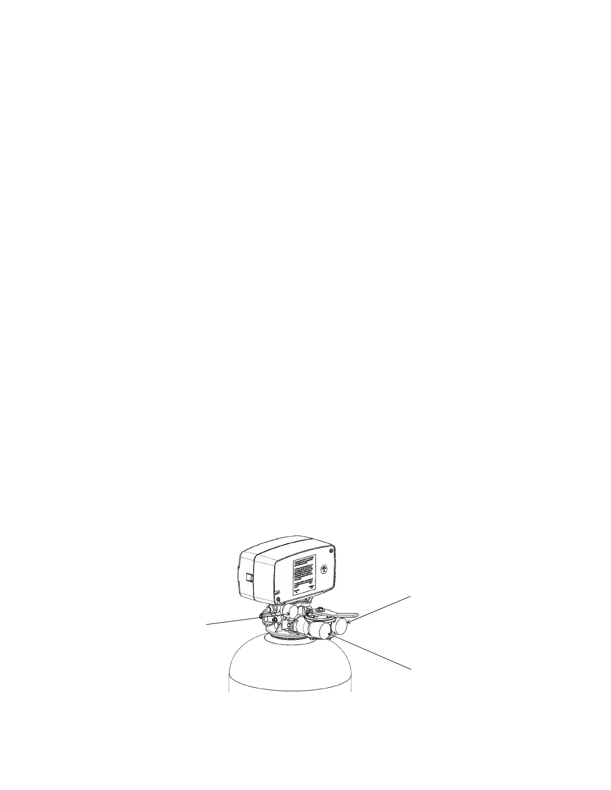
System Inlet
Connection
System Drain
Connection
System Outlet
Connection