Page 4
• The outer barrier will not raise if occupied.
1. Lower the platform to the ground level loading position.
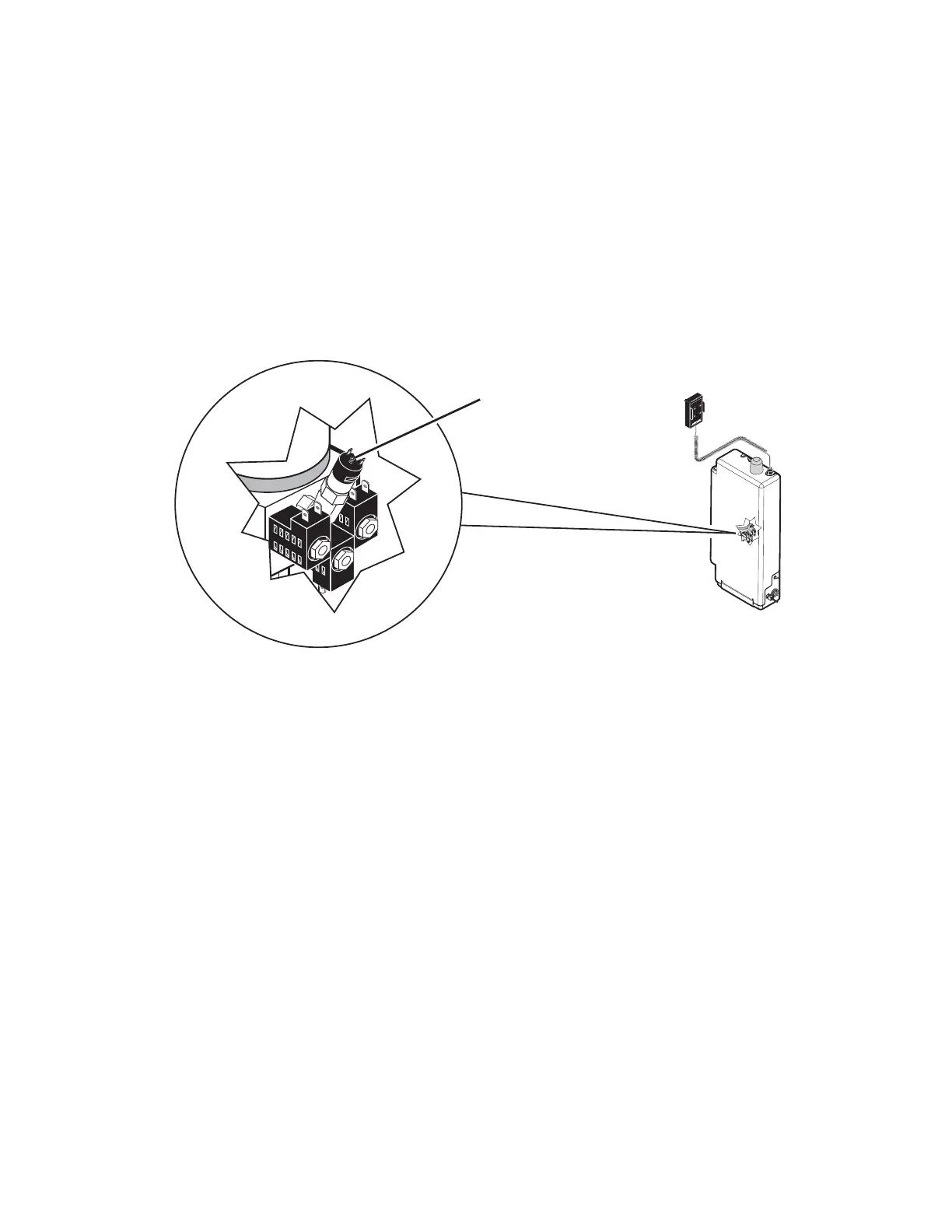
2. Remove the pump cover.
3. Turn the pressure adjustment screw (shown below) counter clockwise until the outer barrier does not
raise when the Up button is pressed.
4. Turn the pressure adjustment screw clockwise in 1/4 turn increments until the outer barrier raises
and fully locks in position when the Up button is pressed. DO NOT turn the pressure adjustment
screw beyond this position.
5. Verify the outer barrier will not raise when occuppied.
6. Reattach the pump cover.
• Verify platform lighting when lift is deployed.
1. Replace bulb(s) in the light housing.
2. Check fuse (5 amp fuse on circuit board; F13)
• An audio warning (and visual warning for public lifts) will activate if the threshold area is occupied when
the platform is a least 1" below floor level.
1. Remove the threshold warning plate
2. Verify the threshold strip switch connectors are connected (see illustration on Page 6)
3. Replace the threshold strip switch
4. Reinstall the threshold warning plate
• Lowering the platform beyond the inner rollstop locking position is allowed only when the inner rollstop is
locked in position.
- Call Product Support.
• Lift platform movement shall be interrupted unless the outer barrier is raised and the outer barrier latch is
positively engaged.
- Call Product Support.
Pressure
Adjustment
Screw
U
NFOLD
F
O
LD
D
OW
N
U
P
Certification Checklist Diagnostic Procedures
 Loading...