Page 3
Use the following adjustment procedures should the lift not function as described in the certification check-
list.These procedures must be followed in order for the lift to be FMVSS 403/404 compliant.
• Vehicle movement is prevented unless the platform is fully stowed.
1. Verify lift stowed signal - pin 7 on the pump module has a +12 volt signal OR pin 9 has a ground
signal (depends on interlock used).
2. Refer to the interlock installation instructions.
• Lift operation shall be inhibited unless the vehicle is stopped and vehicle movement is prevented.
1. Verify vehicle secure signal (pin 6) has a +12 volt signal.
2. Refer to the interlock installation instructions.
• The platform will not fold/stow when occupied.
1. Position the platform at the floor level loading position.
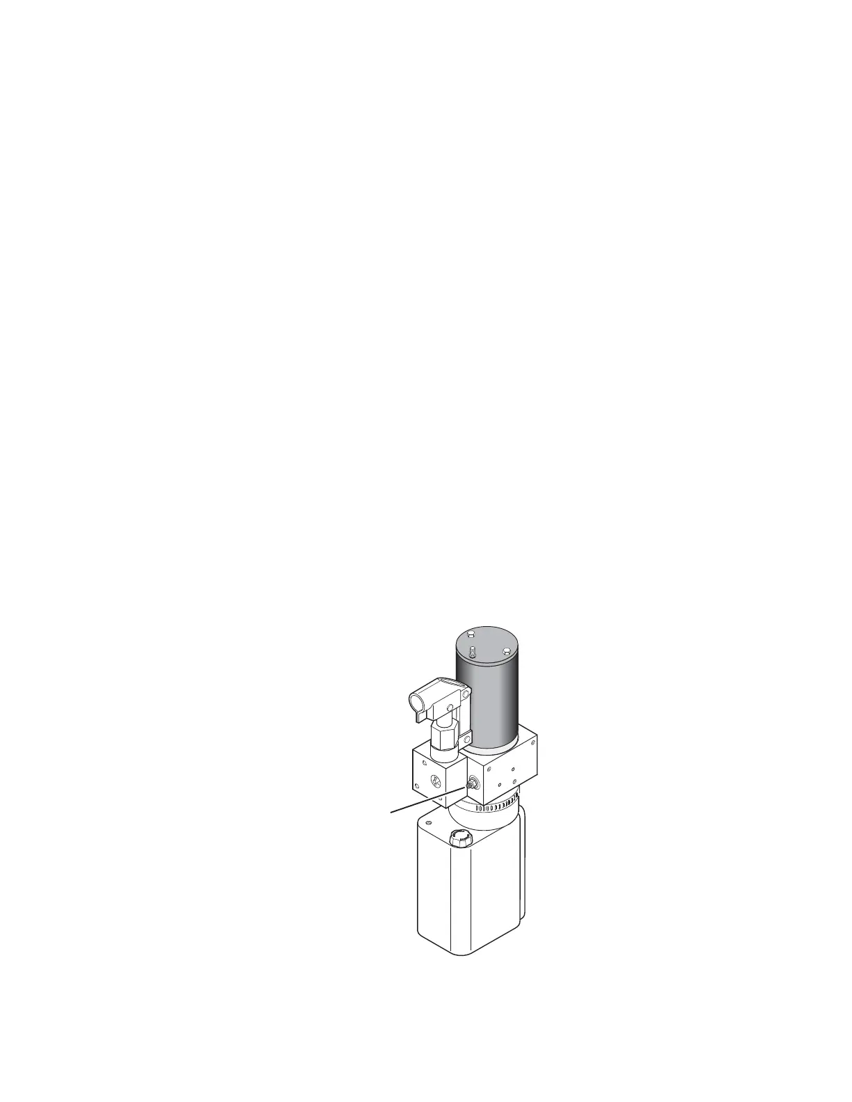
2. Loosen the locknut on the dual relief valve adjustment (do not remove locknut). See illustration be-
low.
3. Turn the adjustment screw counter clockwise until the platform does not fold when the Fold button is
pressed.
4. Turn the adjustment screw clockwise in 1/4 turn increments and press the Fold button until the plat-
form folds completely (Note: return the platform to floor level position after each attempt to fold the
platform).
5. Turn the adjustment screw an additional 1/8 turn after the platform folds successfully.
6. Tighten the locknut without moving the adjustment screw.
7. Verify the platform will not stow while occupied.
• The inner rollstop will not raise if occupied.
- Call Product Support
Platform Relief Valve
Adjustment
(Located beside Backup Pump)
Certification Checklist Diagnostic Procedures
 Loading...