All information herein is proprietary and confidential and may not be copied or reproduced without the expressed written consent of BRAY INTERNATIONAL, Inc.
The technical data herein is for general information only. Product suitability should be based solely upon customer’s detailed knowledge and experience with their
application.
Series 6A Installation, Operation & Maintenance – Field Connections
6A O & M : 10
Natural Gas as an Actuator Medium
The S6A can also be operated with natural gas as an actuator
medium. When operating the positioner with natural gas, you
must follow and adhere to the following safety notes:
1. Only the “EEx ia” version of the positioner and optional
modules with the “EEx ia” type of protection may be
operated with natural gas. Positioners with other types of
protection, i.e. flameproof enclosures for zones 1 and 2 are
not permitted.
2. Do not operate the positioner with natural gas in closed
spaces.
3. Natural gas is continuously blown off in the servo-drive
depending on the model. Special care must therefore be
taken during maintenance activities near the positioner.
Always ensure that the immediate surroundings of the
positioner are adequately ventilated.
4. The mechanical limit switch module may not be used when
operating the positioner with natural gas.
5. Depressurize the devices operated with natural gas
adequately during maintenance activities. Open the cover in
an explosion-free atmosphere and depressurize the device
for at least two minutes.
Normally you operate the positioner with compressed air.
Natural gas has been approved as an actuator medium for
intrinsically safe positioners with the “EEx ia” type of protection.
Only use natural gas which is clean, dry and free from additives.
The positioner releases the used natural gas through the
exhaust air outlet E (see Figure 2). The exhaust air outlet E is
equipped with an attenuator. As an alternative to this standard
configuration, the exhaust air outlet can be replaced with a G¼
screwed fitting. You have to dismantle the attenuator for this
purpose. Natural gas escapes parallel to the exhaust air outlet
E, from the enclosure vent at the bottom side of the device, and
from the control air outlet near the pneumatic connections.
This escaping natural gas cannot be collected and carried off.
When using natural gas as an actuator medium refer to Figure
5 for maximum bleed off values.
6A-6DR5*1*-
*E***
6
A-6DR5*2*-
*E***
Single-acting Double-acting
Bleeding process Operating
m
ode
[
Nl/min] [Nl/min]
Operation,
typical
0.14 0.14
Operation,
max.
0.60 0.60
Bleed the enclosure volume through the bottom
side of the device. Purge air switch is at "IN":
Error case,
max.
60.0 60,0
Operation,
typical
1.0 2.0
Operation,
max.
8.9 9.9
Bleed through the control air outlet near the
pneumatic connections:
Error case,
max.
66.2 91.0
Operation,
max.
Bleed through the exhaust air outlet E
Error case,
max.
358.2
1)
339
1),
32.1 62.1 ]l[ .xaM emuloV
Figure 5. Maximim bleed off values
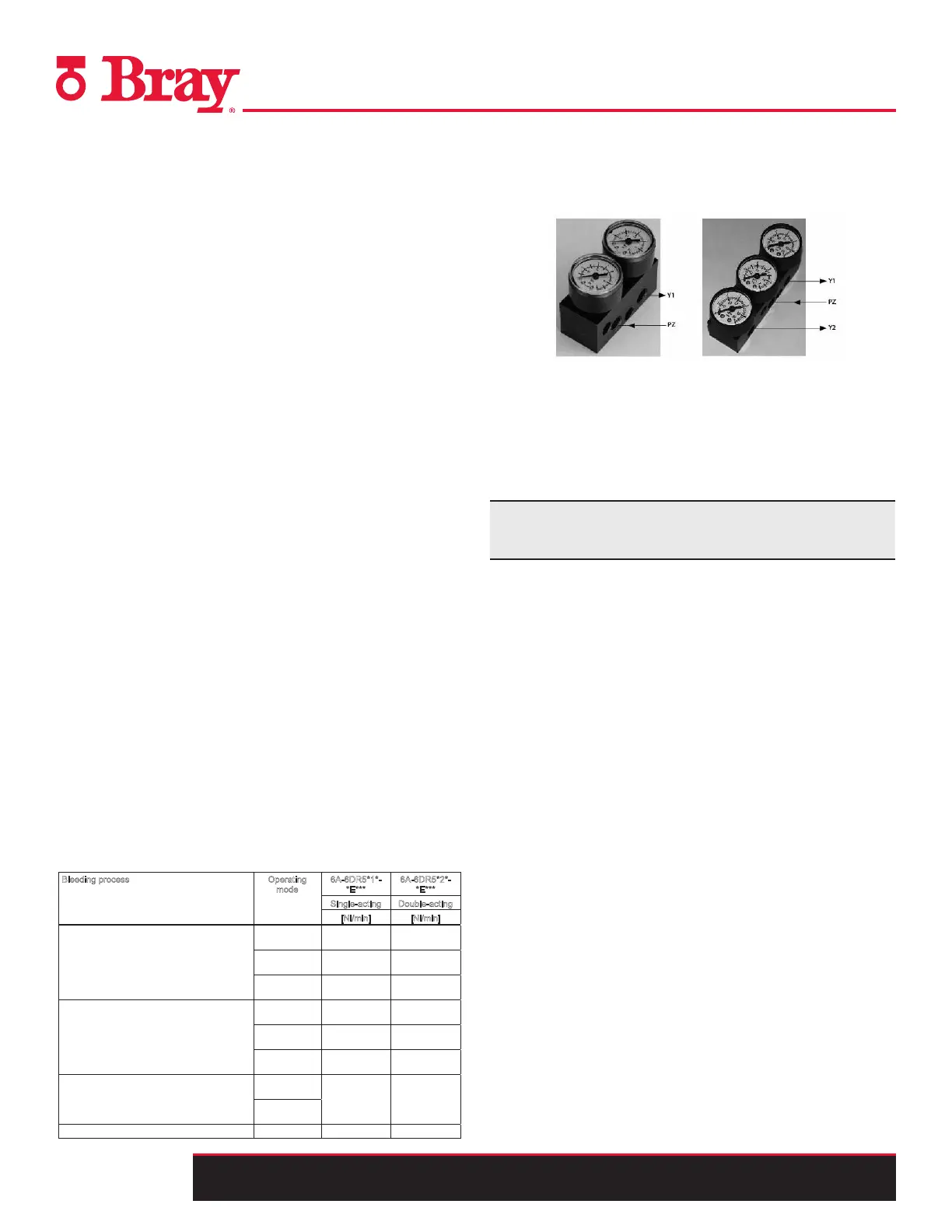
Optional Accessories
1. Pressure Gauges – used to measure and indicate supply
and actuating pressures
2. Filter – used to clean the supply medium
3. Non Contacting/External Position Detection System –
used for harsh environments
4. SIMATIC PDM Operation Software – used for online
diagnostics of the S6A
Contact your Bray representative for specific requirements
for your intended application.

 Loading...

