All information herein is proprietary and confidential and may not be copied or reproduced without the expressed written consent of BRAY INTERNATIONAL, Inc.
The technical data herein is for general information only. Product suitability should be based solely upon customer’s detailed knowledge and experience with their
application.
Series 6A Installation, Operation & Maintenance – Field Connections
6A O & M : 9
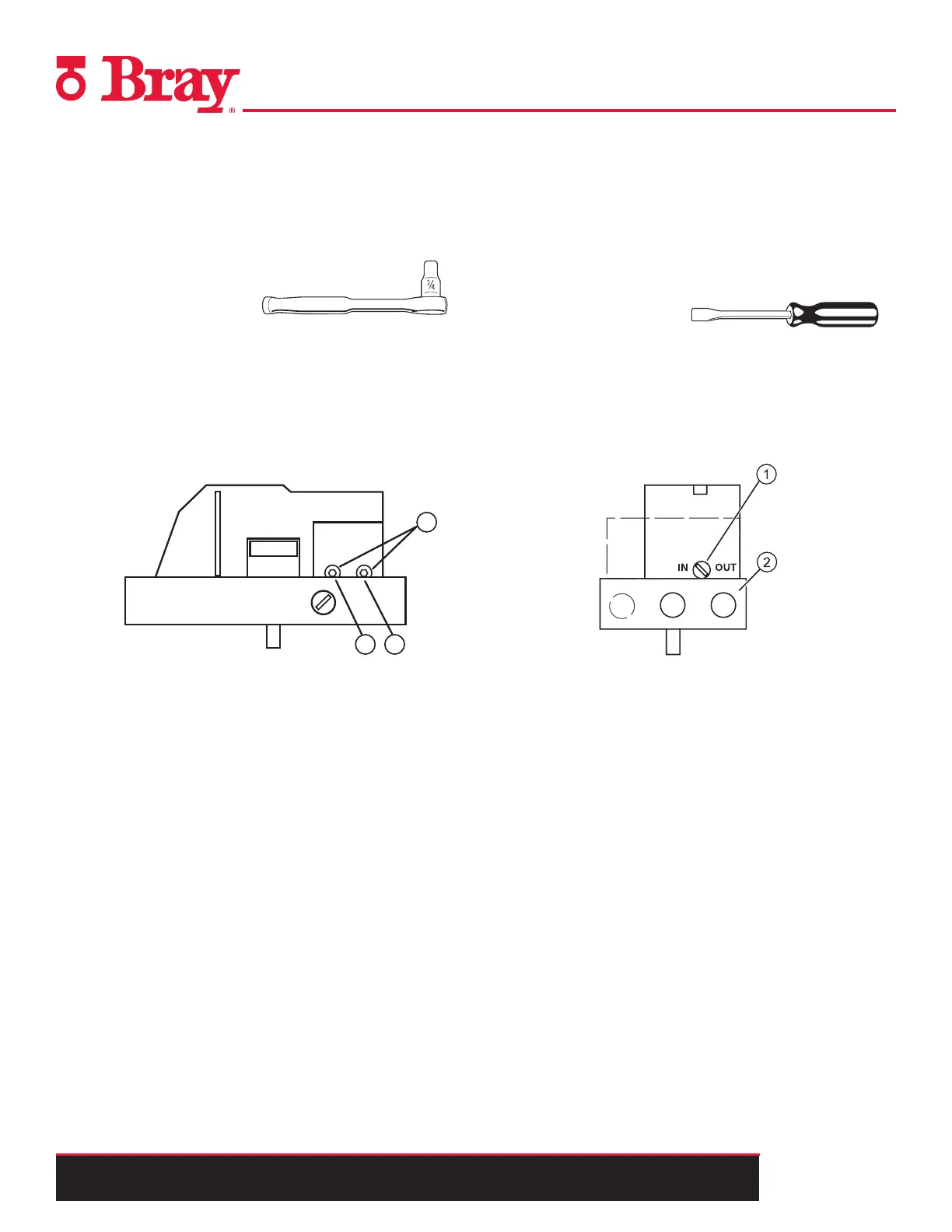
Restrictors
The S6A is equipped with air restrictors to reduce the air output
to achieve actuating times of T > 1.5 s for small actuators.
Restrictors 1 and 2 are used for this purpose.
Tools Needed:
• Hexagon socket 2.5 mm
Refer to Figure 3.
When turned clockwise, they reduce the air output and finally
shut it off.
In order to set the restrictors, it is recommended to close them
and then open them slowly.
In case of double-acting actuators, ensure that both restrictors
have approximately the same setting.
Figure 3. - Air Restrictor
1
Restrictor for Y1
2
Restrictor for Y2, only in the version for double-acting
actuators
3
Hexagon socket-head screw 2.5 mm
Purging
The S6A is equipped with a purge air switch that allows
the actuator to purge air either inside of the unit or directly
outside. When the enclosure is open, the purge air switch
above the pneumatic terminal strip on the pneumatic block
can be accessed.
Tools Needed:
• Instrument Screwdriver
Refer to Figure 4.
In the IN position, the enclosure is flushed from inside with a
small volume of clean and dry instrument air.
In the OUT position, the purge air is directed towards outside
of the unit.
Figure 4. - Purge Air Switch
1 Purge Air Switch
2 Pneumatic Block
 Loading...


