All information herein is proprietary and confidential and may not be copied or reproduced without the expressed written consent of BRAY INTERNATIONAL, Inc.
The technical data herein is for general information only. Product suitability should be based solely upon customer’s detailed knowledge and experience with their
application.
Series 6A Installation, Operation & Maintenance – Field Connections
6A O & M : 6
FIELD WIRING
Each S6A is provided with two conduit entries for power/
incoming analog signal of the main unit and any optional
modules.
Please refer to the wiring diagrams referenced in this doc-
ument when connecting the positioner and any optional
modules. It is essential to install the optional modules before
connecting the positioner electrically. Refer to the following
“Technical Description” portion of this manual for relevant
power distribution sizing information when installing a S6A
positioner and its optional modules.
Safety Notes:
• Local regulations regarding hazardous environments
must be followed when installing this device in a hazard-
ous location.
• The conduit connections must be properly sealed to main-
tain the weatherproof integrity of the actuator enclosure.
• Never connect the current input (terminals 6 and 7 as
shown on the diagrams to the right) to a power source;
the positioner will probably be destroyed in that case. Al-
ways use a current source with a maximum output cur-
rent of I = 20 mA.
• To maintain auxiliary power, the input current must be a
minimum of 3.6 mA.
Note: The plastic enclosure is metallized from inside to
increase the electromagnetic compatibility (EMC) with
respect to high-frequency radiation. The shield is connected
to the threaded bush shown in Figure 1 such that it is elec-
trically conductive. This protection is effective only if you
connect at least one of the bushes to the grounded control
valves through electrically conductive (bare) attachments.
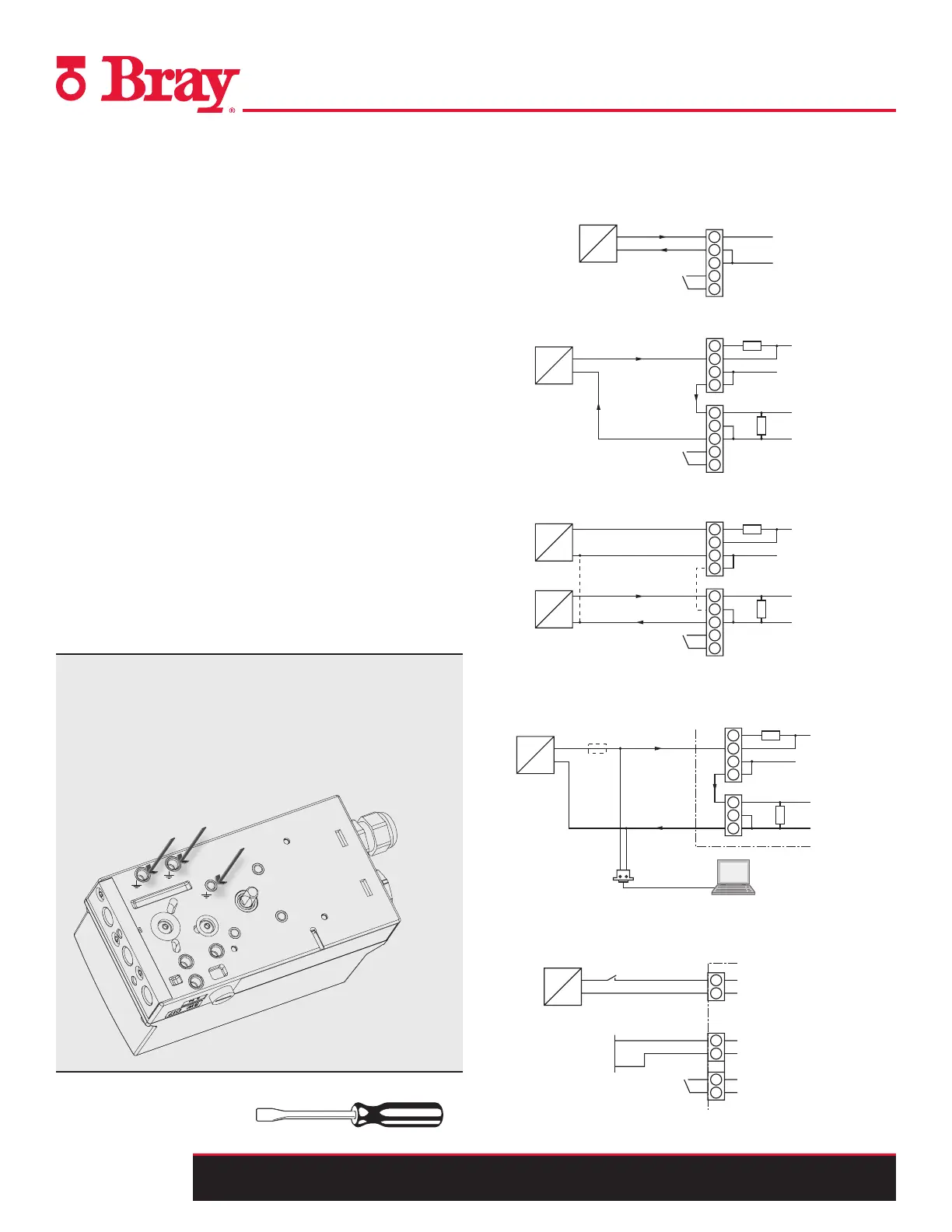
Figure 1.
1.
2.
3.
Tools Needed:
• Instrument Screwdriver
I. General Area
1. Two Wire
4 ... 20 mA
BE1 = Binary Input
7
8
9
10
+
–
J
6
Input for safety shutdown (activated using coding jumper)
1)
≤ 30 V
≤ 24 V
+
–
BE1 = Binary Input
7
9
10
+
–
6
1)
81
82
Input for safety shutdown (activated using coding jumper)
1)
≤ 24 V
–
BE1 = Binary Input
7
9
10
+
–
6
81
82
HART
modem
PC/Laptop
R 250 W if req.
1)
3
Only required with current sources not conforming to HART1)
2
3
4
5
+
–
I
l
y
= 4 ... 20 mA
6
7
8
l
W-
l
H+
1) Jumper between 5 and 7 only for three-wire system
2
3
4
5
+
–
J
6
7
8
9
10
4 ... 20 mA
0/4 ... 20 mA
2
3
4
5
+
–
6
7
8
9
10
18 ... 30 V
J
+
–
BE1 = Binary Input
BE1 = Binary Input
1)
Power Supply
Non-Hazardous Hazardous area, Zone 1
2. Two Wire Connection When Using a 2/3/4 Wire Device
4 ... 20 mA
BE1 = Binary Input
7
8
9
10
+
–
J
6
Input for safety shutdown (activated using coding jumper)
1)
≤ 30 V
≤ 24 V
+
–
BE1 = Binary Input
7
9
10
+
–
6
1)
81
82
Input for safety shutdown (activated using coding jumper)
1)
≤ 24 V
–
BE1 = Binary Input
7
9
10
+
–
6
81
82
HART
modem
PC/Laptop
R 250 W if req.
1)
3
Only required with current sources not conforming to HART1)
2
3
4
5
+
–
I
l
y
= 4 ... 20 mA
6
7
8
l
W-
l
H+
1) Jumper between 5 and 7 only for three-wire system
2
3
4
5
+
–
J
6
7
8
9
10
4 ... 20 mA
0/4 ... 20 mA
2
3
4
5
+
–
6
7
8
9
10
18 ... 30 V
J
+
–
BE1 = Binary Input
BE1 = Binary Input
1)
Power Supply
Non-Hazardous Hazardous area, Zone 1
3. Three/Four Wire
4 ... 20 mA
BE1 = Binary Input
7
8
9
10
+
–
J
6
Input for safety shutdown (activated using coding jumper)
1)
≤ 30 V
≤ 24 V
+
–
BE1 = Binary Input
7
9
10
+
–
6
1)
81
82
Input for safety shutdown (activated using coding jumper)
1)
≤ 24 V
–
BE1 = Binary Input
7
9
10
+
–
6
81
82
HART
modem
PC/Laptop
R 250 W if req.
1)
3
Only required with current sources not conforming to HART1)
2
3
4
5
+
–
I
l
y
= 4 ... 20 mA
6
7
8
l
W-
l
H+
1) Jumper between 5 and 7 only for three-wire system
0/4 ... 20 mA
2
3
4
5
+
–
6
7
8
9
10
18 ... 30 V
J
+
–
BE1 = Binary Input
1)
Power Supply
Non-Hazardous Hazardous area, Zone 1
4. HART
4 ... 20 mA
BE1 = Binary Input
7
8
9
10
+
–
J
6
Input for safety shutdown (activated using coding jumper)
1)
≤ 30 V
≤ 24 V
+
–
BE1 = Binary Input
7
9
10
+
–
6
1)
81
82
Input for safety shutdown (activated using coding jumper)
1)
≤ 24 V
–
BE1 = Binary Input
7
9
10
+
–
6
81
82
HART
modem
PC/Laptop
R 250 W if req.
1)
3
Only required with current sources not conforming to HART1)
2
3
4
5
+
–
I
l
y
= 4 ... 20 mA
6
7
8
l
W-
l
H+
1) Jumper between 5 and 7 only for three-wire system
2
3
4
5
+
–
J
6
7
8
9
10
4 ... 20 mA
0/4 ... 20 mA
2
3
4
5
+
–
6
7
8
9
10
18 ... 30 V
J
+
–
BE1 = Binary Input
BE1 = Binary Input
1)
Power Supply
Non-Hazardous Hazardous area, Zone 1
5. Profibus DA/DP, Foundation Fieldbus
4 ... 20 mA
BE1 = Binary Input
7
8
9
10
+
–
J
6
Input for safety shutdown (activated using coding jumper)
1)
≤ 30 V
≤ 24 V
+
–
BE1 = Binary Input
7
9
10
+
–
6
1)
81
82
Input for safety shutdown (activated using coding jumper)
1)
≤ 24 V
–
BE1 = Binary Input
7
9
10
+
–
6
81
82
HART
modem
PC/Laptop
R 250 W if req.
1)
3
Only required with current sources not conforming to HART1)
2
3
4
5
+
–
I
l
y
= 4 ... 20 mA
6
7
8
l
W-
l
H+
1) Jumper between 5 and 7 only for three-wire system
2
3
4
5
+
–
J
6
7
8
9
10
4 ... 20 mA
0/4 ... 20 mA
2
3
4
5
+
–
6
7
8
9
10
18 ... 30 V
J
+
–
BE1 = Binary Input
BE1 = Binary Input
1)
Power Supply
Non-Hazardous Hazardous area, Zone 1

 Loading...

