BRAY Series 70 Electric Actuator
Operation and Maintenance Manual
14
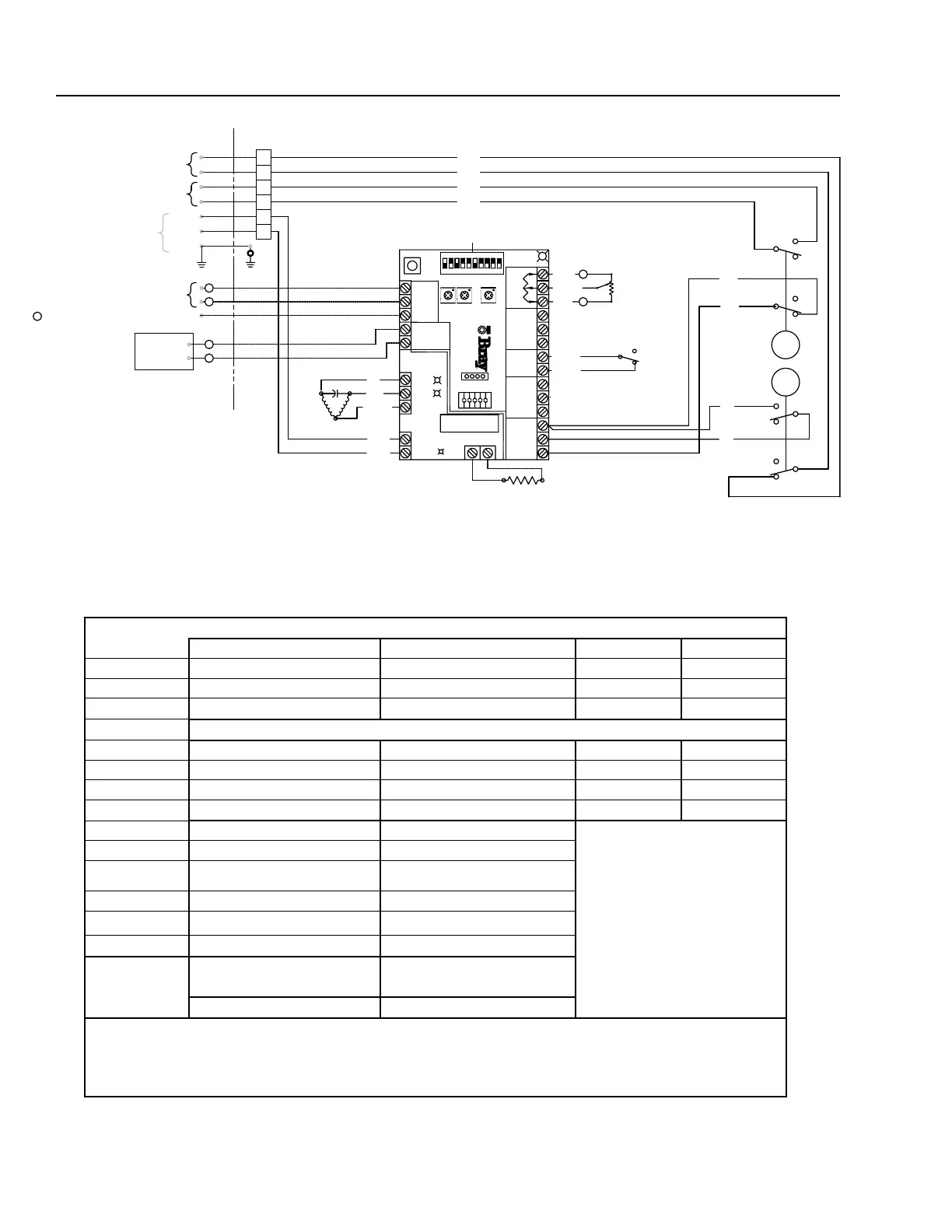
NOT TO EXCEED
500 OHMS
FIELD WIRING
5 VDC AT 50mA (IF REQUIRED)
POSITION
FEEDBACK
DEVICE
LOAD DEVICE
INCOMING COMMAND SIGNAL
+
OUTGOING FEEDBACK SIGNAL
-
+
NEUTRAL
LIVE
MOTOR
N
C
OR BLACK
YELLOW
O
ACTUATOR
RED
BLUE
POTENTIOMETER
GREY
+
OVERRIDE SW
WHITE
ORANGE
-
YELLOW
YELLOW
FEEDBACK
COM
N.O.
N.C.
MANUAL
AUX CLOSE
COM
N.O.
CLOSE
N.C.
N.O.
AUX OPEN
GREEN
CAM
COM
RED
CAM
N.C.
OPEN
COM
N.C.
N.O.
N.C.
COM
N.O.
BLUE
C
BLUE
D
B
A
RED
RED
(VOLTAGE FREE)
(VOLTAGE FREE)
CLOSE N.O.
OPEN N.O.
BLUE
BLUE
RED
RED
HEATER
(OPTIONAL)
(SEE NOTE 3)
MOTOR
OPEN
1
ON
MOTOR
CLOSE
FUSE
NEUTRAL
NEUTRAL
LINE
Power
OUTPUT (+)
OUTPUT (-)
+5 VDC
INPUT (+)
INPUT (-)
OPEN
LIMIT
CLOSE
LIMIT
COMMON
COMMON
HANDWHEEL
CALIBRATE
STATUS
+5 VDC
COMMON
FB POT
HIGH
VOLTAGE
SERVO
2
10987
6543
PRO
HEATER
DEAD BAND
CLOSE
SPEED
OPEN
SPEED
CLOSE
OPEN
COMMON
TORQUE LIMIT
CLOSE
OPEN
COMMON
CONTROL BOX
S10
S9
S8
S7
S6
S5
S4
S3
S2
S1
E
F
GROUND
SINGLE PHASE
POWER SUPPLY
WHITE
BLACK
-
+
CALIBRATION SEQUENCE:
1. SET TRAVEL LIMIT SWITCHES
TO DESIRED END OF TRAVEL POSITIONS.
2. CONNECT POWER SUPPLY.
3. WITH ACTUATOR AT MID TRAVEL
PRESS "CALIBRATE" BUTTON FOR TWO SECONDS.
4. ACTUATOR WILL SELF-CALIBRATE.
DIP SWITCHES
Warning: Turn aLL PoWer off Prior To adjusTing diP sWiTches.
SWitch
cOMMand inPut
4-20 mA DC 0-5 Vdc * 0-10 Vdc 2-10 Vdc
1 Off On On
On
2 Off Off On
On
3
Off Off Off
On
OutPut
4-20 mA DC 0-5 VDC 0-10 VDC 2-10 VDC
4 Off On On
N/A
5 On Off Off
N/A
6
Off On Off
N/A
fOrWard acting reVerSe acting
7 Off On
fail in
laSt POSitiOn
fail enable **
8 Off On
fail clOSe fail OPen
9 Off On
tOrque tOrque
SWitch enable SWitch diSable
10
Off On
*To control servo with a remote potentiometer, set the Command Input to 0-5VDC (see Command Signal Connector section;
page 8 Servo Pro Manual).
**Fail position is the position that the servo will travel to when the control signal is removed. It does not apply to 0-5VDC or
0-10VDC Command Signals.
 Loading...


