Series 98 & 98H Scotch Yoke Actuator
Installation, Operation and Maintenance Manual
© 2020 BRAY INTERNATIONAL, INC. ALL RIGHTS RESERVED. BRAY.COM The Information contained herein shall not be copied, transferred,
conveyed, or displayed in any manner that would violate its proprietary nature without the express written permission of Bray International, Inc.
71 of 84
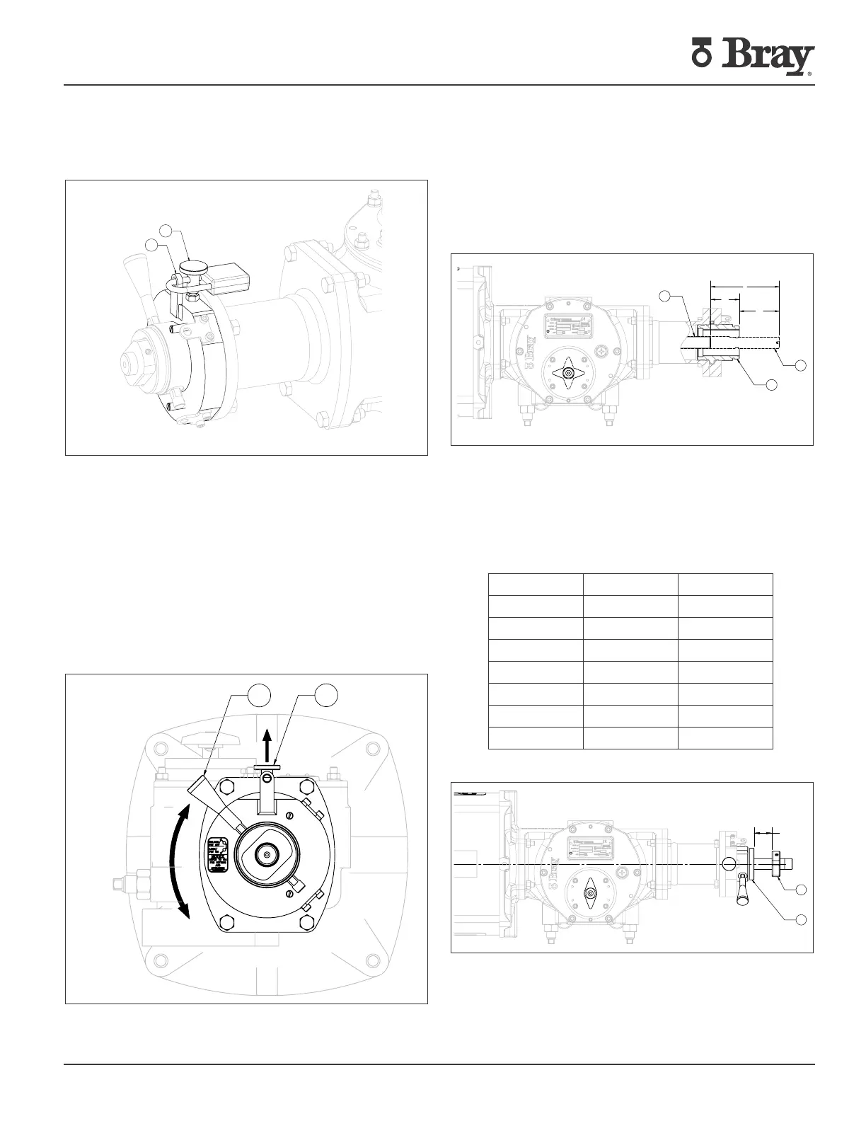
9. The two indexed positions of the device can be physically
locked with a padlock through the indexing plunger knob
(23), to prevent inadvertent or unauthorized operation of the
device.
23
4
Fig. 57
19.3 Configuring as Locking Device at CCW end
At times, the valve is required to be locked in the
counterclockwise end position, which is usually the valve’s
open position. The locking device on S98 is capable of being
configured to do this as well.
1. First, ensure the travel stops on the actuator have been set
and locked to the valve’s requirement. Turn the actuator to
its CW end position and turn the handle (7) on the device
upwards to the UNLOCKED position, if not already in this
position. Ensure the position is secured by the indexing plunger
sitting in and the handle will not turn in this indexed position.
23
7
UNLOCK/
PST OFF
LOCK/
PST ON
Fig. 58
2. Measure the total stroke (S) of the Extension rod (2).
Turn the actuator to its CW end position and measure the
projected length of the Extension rod end from the sleeve
face. Next, operate the actuator to CCW position and
measure the depth of the Extension rod face from the
sleeve face. Add the two to get the total stroke length.
S=L1+L2.
L1
L2
S
2
4
2
Fig. 59
3. Loosen the locknut (3) by first slackening the set screws
(11). Set the distance "L" between the index sleeve's outer
face and the inner face of the locknut per the below table.
L=S-A, mm
S, Stroke Measured, mm
Sl No Model A, mm
1 12E2 60
2 18E2 74
3 45E2 97
4 73E2 118
5 14E3 140
6 24E3 191
7 45E3 234
Fig. 60
L
3
4
4. Return the actuator to the CW end. Turn the locknut a bit
clockwise to align the locknut's flat faces to the sleeve's flat
sides, so that the sleeve's profile will not interfere with the
locknut when the extension rod moves inwards. Lock the set


 To Next Page