11
Chapter 1: Hardware insertion and Bed Cabinet assembly.
Chapter 1: Hardware insertion and
Bed Cabinet assembly.
REQUIRED TOOLS
• Rubber Mallet
• Cordless Drill with #2 Phillips
• Magnetic Bit Holder (For Drill)
• #1 Phillips Screwdriver
REQUIRED HARDWARE
• Hardware Package #1
• Hardware Package #6
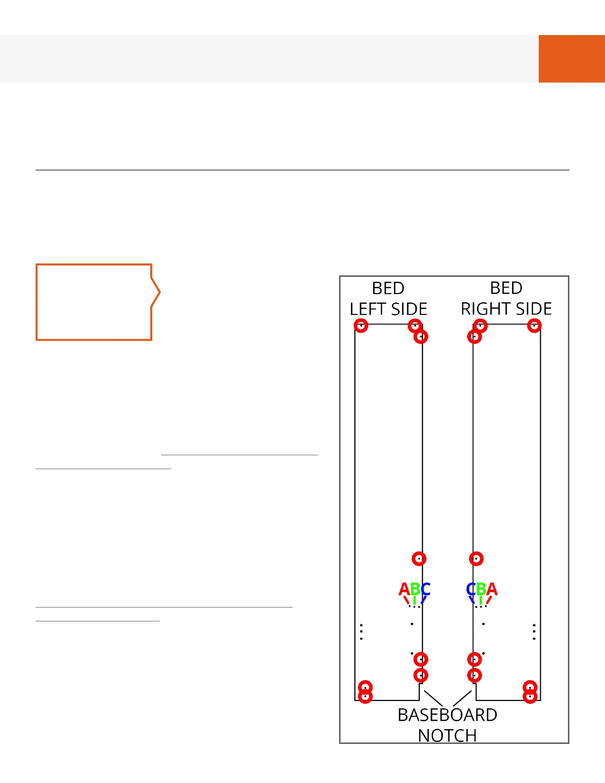
FIG. 1A
STEP 1
Referring to Fig. 1A,
lay “Bed Cabinet
Left Side” and “Bed
Cabinet Right Side”
on oor and insert
cam screws from
hardware package #1 in holes marked with
a red circle using the cordless drill.
BredaBeds Murphy Beds are designed
for a mattress thickness of 11” or under,
however Headboard area ABC/CBA is
adjustable for mattress thicknesses greater
than 11” if needed. In this area, use only 1
cam screw per side:
• Holes ‘A’ (closest to panel midpoint) are
for an 11” thick mattress.
• Holes ‘B‘ (middle) are for a 12” thick
mattress.
• Holes ‘C’ (hole closest to panel edge) are
for a 13” thick mattress.
Even though we provide this adjustment,
we highly recommend using a mattress
that is 11” or under so that the headboard
will sit at an angle to minimize the gap
between the wall and the mattress. Thus
we recommend using holes ‘A’.
If the side panels on your bed have only 1
hole in this area then your headboard is
not adjustable and you will use the only
hole available.