32
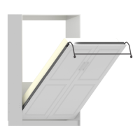
Chapter 7: Final adjustment for the Bed Cabinet and springs.
To determine the proper tension, the mattress needs to be in
place. The face assembly should raise and lower with about
10 pounds of pressure and bed legs should rest on the oor
without lifting when bed is open.
If the bed is too heavy to operate, springs must be added
to achieve the proper balance. The easiest way to add springs is to remove the
Bed Face Panel (see the note on the previous page about removing the Bed Face
Panel).
If the bed lifts o the oor or slams shut, springs must be removed to achieve the
proper balance. Springs can be removed by one of two ways: The Bed Face Panel
can be removed, which is the recommended way (see the note on the previous
page about removing the Bed Face Panel) or they can be removed or cut with bolt
cutters from inside the bed cavity. To remove spring from inside the bed cavity,
remove the mattress and have one person climb in near the mechanism, have the
second person close the bed face assembly to relieve some of the spring tension.
Once the spring is removed, re-test the tension.
STEP 2
The labels/stickers can now be removed from all parts. We
use EZ peel-o labels for quick and residue free removal.
DO NOT remove the warning label on the “Bed Cabinet
Top Nailer”. The parts can be wiped clean with a damp cloth.
Ax the clear sleeve envelope to the backside of the Bed Face
Panel and store your instructions there for future use.
STEP 4
You may notice that you have extra hardware once assembly has been
nished. This is normal, we provide extra hardware with each bed model as
a convenience. Once assembled, you can safely discard this hardware.
Now that assembly has been completed, we hope that your
BredaBed will bring you many years of enjoyment! Contact us
if you ever have any questions.
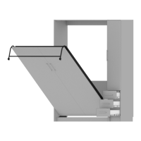
If the beds squeak during
rotation, the pivot points can be
lubricated with WD-40 or silicone
spray. Once sprayed, you should
open and close the bed several
times to work in the lubricant.
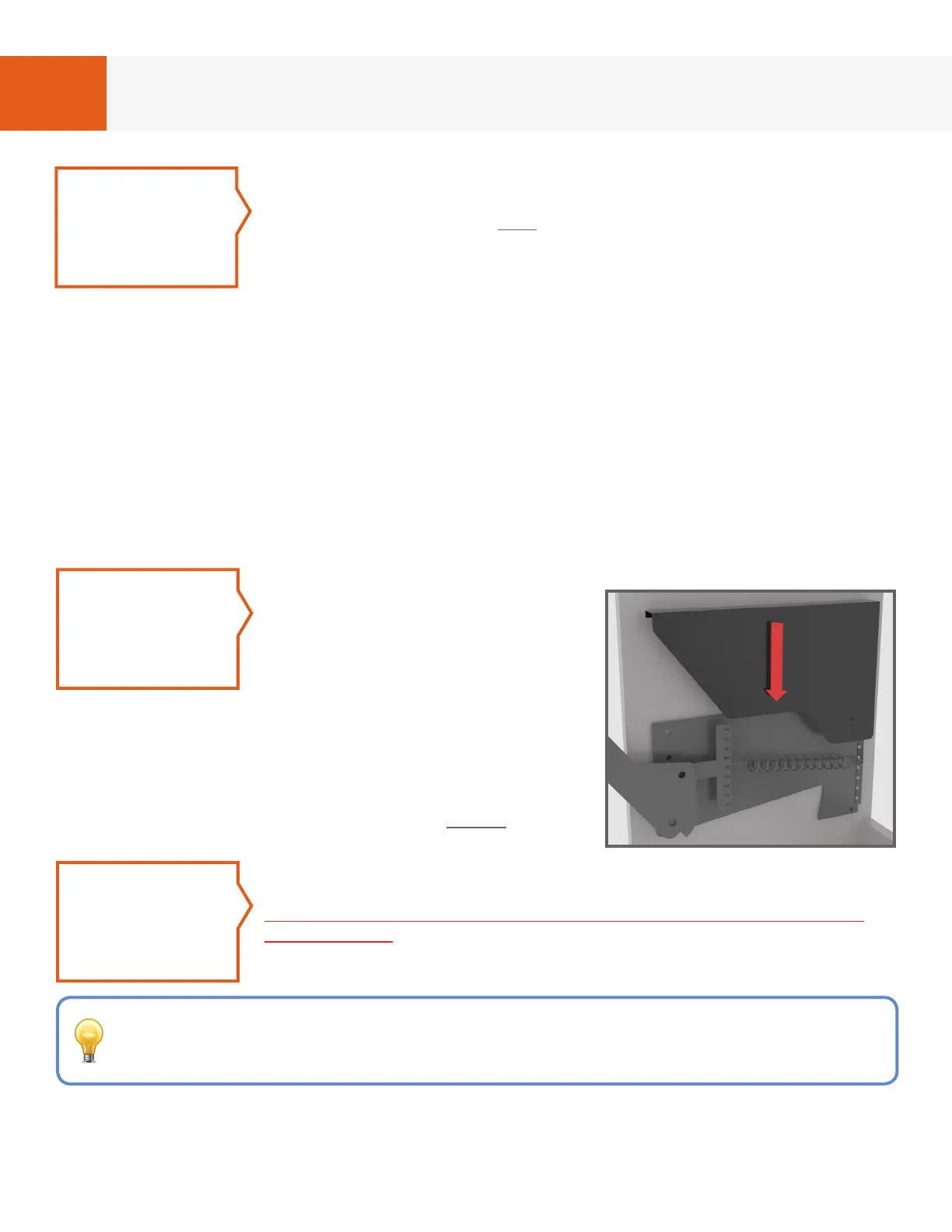
Align the steel mechanism cover to the mechanism
and then slide downward. The top of the cover will
wrap around the mechanism with the two holes
towards the bottom. In the bottom hole (the hole that
aligns with the cylinder) insert 1 black wood screw
(#8 x 1 1/2”) from hardware card #2 to secure.
STEP 3
FIG. 7A - LEFT SIDE COVER