6
Intended Usage
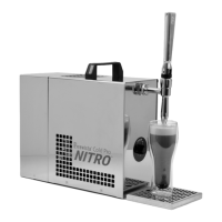
The Brewista® Cold Pro Nitro™ Dispenser is a ready-to-use dispenser to tap nitrogenized
and cooled beverages in parcular cold-brew coee. Such systems are mainly used for
professional customers in hotels, restaurants and bars. The nitrogen eect is created
through ltered compressed air which contains 78% nitrogen. The device is only approved
for this applicaon and is not suitable for cooling hot liquids, unltered liquids, chemicals, or
similar substances.
Operaon Instrucons
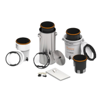
Assemble your Cold Pro™ Nitro
1) Place the device in a level, clean, and dry locaon.
2) Screw on tap components to the tap [(1), (2), and (3)] and secure handle (1)
with locknut.
3) Place the drip tray (6) in front of the unit. Remove the protecve lm and
discard.
4) Turn the temperature control (5) clockwise to maximum (7 o’clock posion).
5) Put air-compressor switch (marked with PRESSURE) (16) to “O” (o).
6) Plug in the power cord (17) to a grounded outlet (refer to Addional Safeguards,
page 3).
Connect the Intake Line
1) To connect the intake line (11) to the dispenser a coupler system is used. Simply
push the male and female parts together.
2) To release the intake line, push the metal spring component.
• If the intake line is too long, reduce the length with a clean smooth cut.
• If you want to increase the cooling power of your system you can assemble
an addional cooler in your intake line and an addional lter must be used
(see next point).
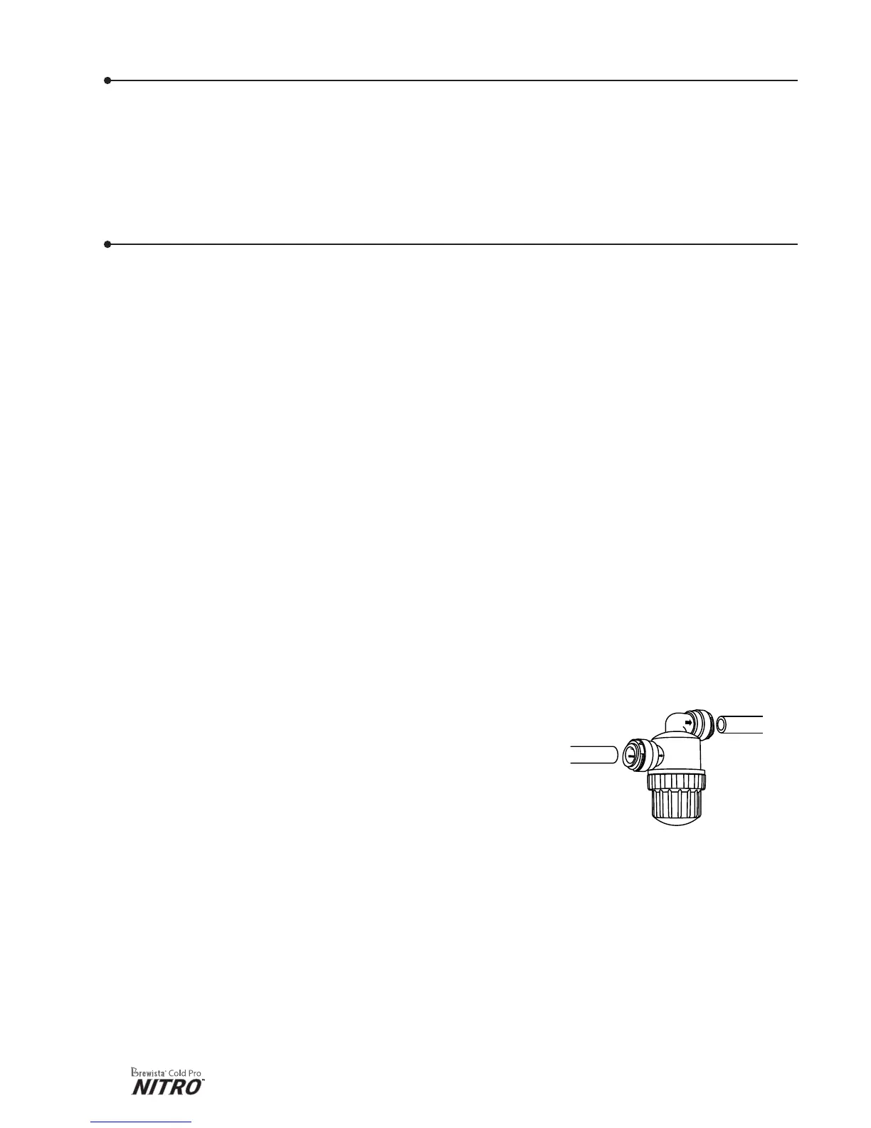
3) To assemble the lter adapter:
• Make a perpendicular cut across the tubing to be connected.
• Remove any burs or sharp edges.
• Ensure the outer diameter is free of score marks.
• For so or thin-walled tubing, use a tube insert for
added strength and stability.
• Push the tube into the ng.
• Pull on the tubing to check that it is secure. Test the
system before use.
• Verify the ow is in the direcon of the arrows noted on intake lter.
• To disconnect tubing: ensure the system is depressurized, push and hold the
collet square against the ng to remove the tube.
• Note: If a lter adapter is not part of your intake line, coee grounds
or other parcles could block the jet nozzles in the device or impair the
funconality of the membrane pump and make the device unusable.
4) Make sure the intake line (11) is pushed into its the socket (15) rmly.