5
Components and functions
3
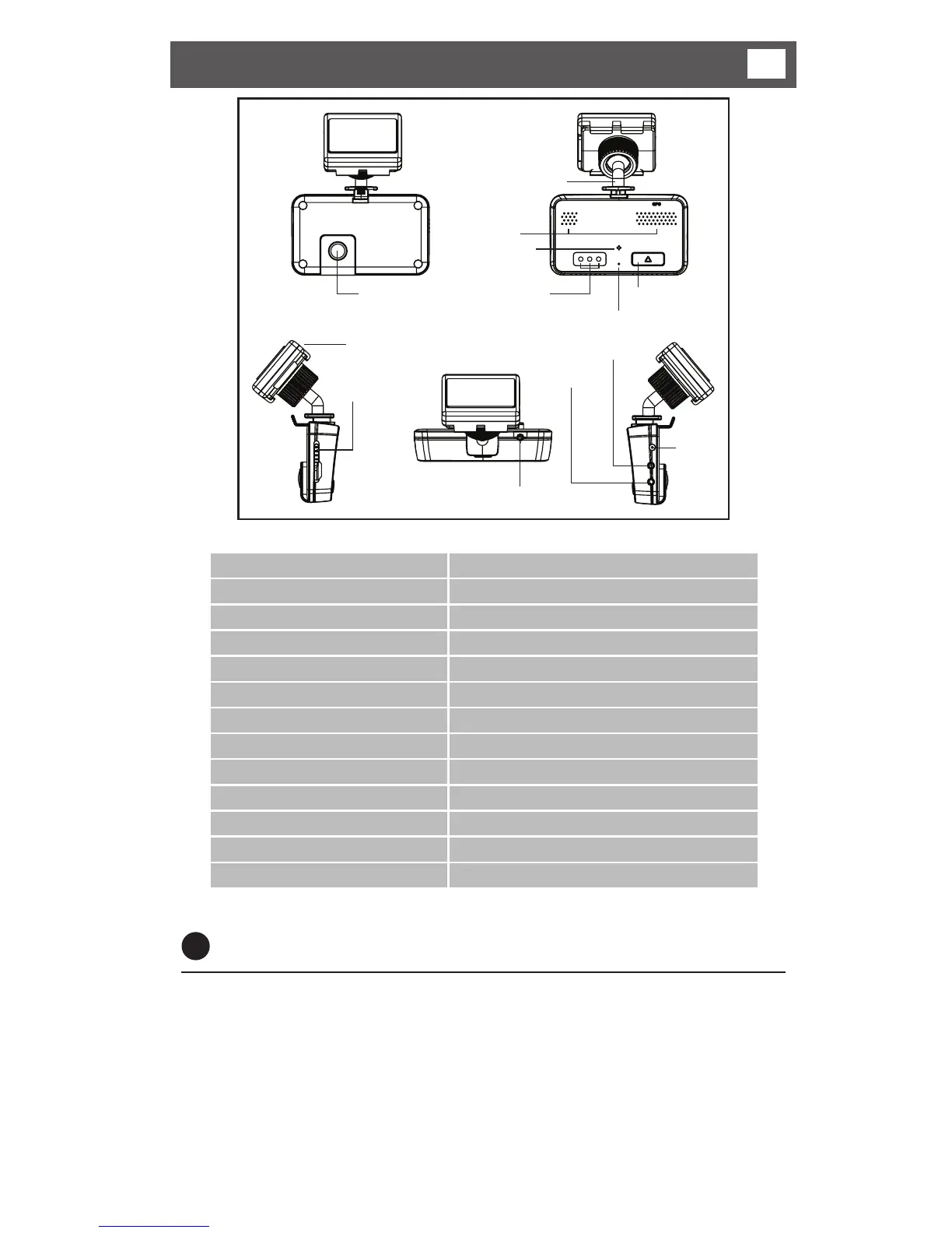
1. Camera
8. micro SD slot
12. GPS antenna
11. External GPS input
2. V-Out
4. DC in
3. External camera input
13. Mounting Bracket
7. Speaker
6. Microphone
5. Status LED
10. Reset button
9. Function button
1
Power connections
*Connect the red wire to a 12-24V supply (ensure supply circuit is fused).
Connect the black wire to a suitable vehicle ground.
Connect the DC Jack to the DC connection of the recorder.
There is an optional cigar lighter power cable available to power the recorder from
a vehicle cigar lighter socket.
* If you connect to a permanent supply be aware that the vehicle battery may
become discharged over time.
1. Camera 2.0M Pixel CMOS CAMERA
2. V-OUT Video output connection
3. CAM (Input) External Camera input connection
4. DC IN (Power Input) Connects the power cable (DC 12V~24V)
5. Status LED Power & GPS/Recording/Audio Status indication
6. Microphone Audio recording microphone
7. Speaker Output speaker for audible warnings
8. Micro SD Card Slot A slot for inserting the micro SD Card
9. Function Button Emergency recording, Audio recording ON/OFF
10. Reset Button System reset button
11. GPS Input GPS signal input connection
12. GPS antenna
13. Mounting Bracket