35
Governor Systems
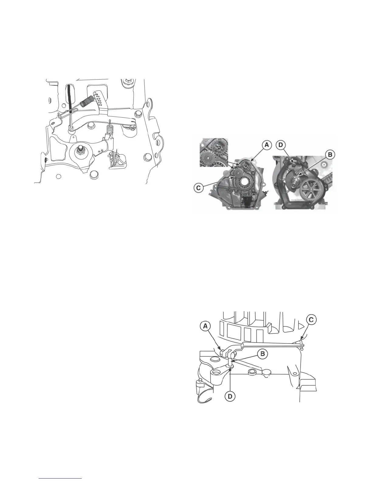
Linkage and Spring Orientation
NOTE: Be sure to note hole position of linkage before removing.
Figure 39
Governed RPM Limits
To comply with specifi ed top governed speed limits, Briggs &
Stratton supplies engines with an adjustable top speed limit,
which the equipment manufacturers set to their own specifi -
cations.
Top governed speed should be checked with a tachometer
when the engine is operating on a completely assembled unit.
The equipment should be operated under no load when mak-
ing these checks.
If a governor spring must be replaced, consult the appropri-
ate Illustrated Parts List for the correct part number.
After a new governor spring is installed, check the engine top
governed speed with an accurate tachometer, as noted above,
and adjust as required.
The mechanical governor is part of the crankcase cover.
The governor gear (A, Figure 40) is driven by the crankshaft
timing gear (B) through an idler gear (C). The governor crank
(D) is mounted in the cylinder assembly.
NOTE: Stamped side of idler gear faces out.
Disassemble
1. Drain oil from engine. Remove burrs and clean
crankshaft, then remove crankcase cover. Set aside.
2. Loosen governor lever nut (A, Figure 41).
3. Slide lever off governor crank (B) and disconnect from
governor link (C).
4. Remove push nut and washer (D) from governor crank.
Remove any burrs from governor crank, and then
remove crank from inside cylinder.
Governor Service
Figure 40
Figure 41
 Loading...