EasyManua.ls Logo

Briggs & Stratton GC1031 - User Manual

Briggs & Stratton GC1031
32 pages
Print Icon
To Next Page IconTo Next Page
Loading...
Not for
Reproduction
Page | i
Operation Instructions
GC1031
GENSET Controller
Copyright © Briggs &Stratton Corporation 80086364
Milwaukee, WI USA. All Rights Reserved. Revision A

Questions and Answers

  • D
    Dr. Tom BaileyAug 19, 2025
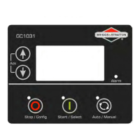
    Why does my Briggs & Stratton GC1031 display incorrect PF N value or kW or load current?
    • T
      Toni OrtizAug 19, 2025
      If the Briggs & Stratton Controller displays an incorrect PF N value, kW, or load current, verify the wiring of the alternator phase voltage and the CT to the controller. Also, if the kW or current reading is faulty, check the CT ratio.
  • K
    Kevin CaldwellAug 21, 2025
    Why is my Briggs & Stratton Controller displaying incorrect Mains voltage or incorrect main alternator voltage?
    • J
      Jessica MillerAug 21, 2025
      If the Briggs & Stratton Controller displays an incorrect Mains voltage or incorrect main alternator voltage, check the wiring of the respective phase to the controller.
  • M
    misty01Aug 23, 2025
    What to do if my Briggs & Stratton Controller generates unnecessary “Shutdown Alarms” or “Warning Alarms”?
    • J
      Jason FreemanAug 23, 2025
      If the Briggs & Stratton Controller generates unnecessary “Shutdown Alarms” or “Warning Alarms”, check the respective switch/sensor and wiring. Also, verify the respective threshold configuration in the controller's “Configuration Mode”.
  • V
    Veronica MorseAug 26, 2025
    Why does my Briggs & Stratton GC1031 Controller display incorrect engine RPM?
    • J
      Jeffrey JenkinsAug 26, 2025
      If the Briggs & Stratton Controller displays an incorrect engine RPM, check the MPU connection and configuration (if enabled). Also, check the wiring of the main alternator’s R-phase and neutral to the controller.
  • J
    Jackson RiveraAug 28, 2025
    How to troubleshoot a Briggs & Stratton GC1031 that does not power ON?
    • T
      Taylor MillerAug 28, 2025
      If the Briggs & Stratton Controller does not power on, check the battery voltage, the fuse on the battery supply, the continuity between battery positive and controller terminal # 2, and the continuity between battery negative and controller terminal # 1.
  • D
    Donald ClarkAug 30, 2025
    What to do if my Briggs & Stratton Controller fails to crank-start the engine?
    • B
      Brianna SmithAug 30, 2025
      If the Briggs & Stratton Controller fails to crank-start the engine: * Check the battery voltage. * Enter “Configuration Mode” and verify the configuration for the “START” output, ensuring the “START” output is working correctly by measuring its output voltage. * Enter “Configuration Mode” and verify the configuration of the “CRANK DISCONNECT” method.
  • C
    Christopher GonzalesSep 2, 2025
    Why does my Briggs & Stratton Controller show genset to be “OFF” when the engine is running?
    • J
      Jason FernandezSep 2, 2025
      If the engine runs, but the Briggs & Stratton Controller shows genset to be “OFF”, check if the MPU signal (if used), and main alternator voltage signal (R/L1 phase) are received by the controller terminals. Also, check if the LOP and LLOP are working correctly and verify their wiring to the controller.
  • B
    Brian HarrisSep 4, 2025
    How to fix a Briggs & Stratton GC1031 Controller that does not maintain the target RPM?
    • C
      Christina WhiteSep 4, 2025
      If the Briggs & Stratton Controller does not maintain the target RPM, the engine RPM is not stable, or the engine hunts, and the controller cranks the engine but does not start it, perform the following checks: 1. Check the wiring of the actuator to the controller's terminal. 2. Check if the mechanical linkage assembly is OK. 3. Enter “Configuration Mode” and verify the configuration for “GOVERNOR”. Also, check the PID control gains. 4. Check that the Actuator moves to full throttle position when the engine is cranked.
  • A
    Austin CraneSep 6, 2025
    Why does the “Emergency Stop” alarm come up on my Briggs & Stratton GC1031 when the “Emergency Stop” is not pressed?
    • S
      smithsandraSep 6, 2025
      If the “Emergency Stop” alarm appears on the Briggs & Stratton Controller even when the “Emergency Stop” is not pressed, check if the “Emergency Stop” switch is working correctly, including its wiring. Also, verify the configuration of “EMERGENCY STOP” polarity in the “Configuration Mode”.
  • B
    Beverly DavisSep 8, 2025
    What to do if Briggs & Stratton GC1031 displays incorrect reading for any of LOP, Fuel Level, Temperature sensors?
    • K
      kenneth49Sep 8, 2025
      If the Briggs & Stratton Controller displays incorrect readings for any of LOP, Fuel Level, or Temperature sensors, check the respective sensor and its wiring. Also, enter “configuration mode” in the controller and verify the calibration for the respective sensor in configuration.

Summary

Installation and Terminal Description

1.1 Terminal Description

Describes the rear view of the controller and its terminals, detailing connections.

Description of Control Keys

2.1 Functions of Control Keys

Overview of control key functions and their behavior in different operating modes.

Configuration of GCU

3.1 List of Parameters

Provides a comprehensive overview of configurable parameters for the GC1031 controller.

Operating Modes

4.1 Auto Mode

Details on operating the genset in automatic mode, covering various conditions for start/stop.

4.1.1 Auto Mains Failure (AMF)

Explains the Auto Mains Failure (AMF) mode functionality for automatic mains takeover.

4.1.2 Remote Start;Stop (2 Wire)

Instructions on using the remote start/stop feature via a 2-wire connection.

4.1.3 Auto Exercise Mode

Information on the automatic genset exercise mode for periodic maintenance runs.

4.2 Manual Mode

Instructions for operating the genset manually via keypad input and control.

4.2.1 Low Idle Mode (LIM)

Explanation of the Low Idle Mode (LIM) for running the genset at reduced speed.

Alarms

Troubleshooting and Safety Warnings

Autostart Hazard Warning

Warning about autostart hazard and essential safety precautions before servicing.

Electric Shock Hazard Warning

Warning about electric shock hazard and mandatory safety measures during installation/servicing.

Briggs & Stratton GC1031 Specifications

General IconGeneral
BrandBriggs & Stratton
ModelGC1031
CategoryController
LanguageEnglish

Related product manuals