17
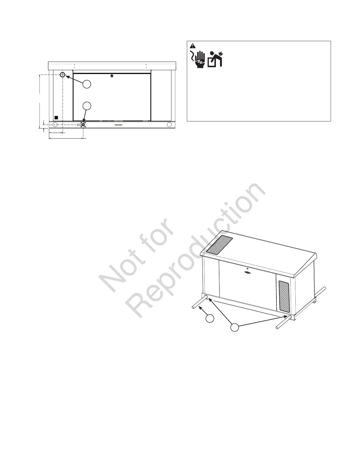
Electrical and Fuel Inlet Locations
The 1 inch N.P.T. fuel inlet connector (A) and 2 inch electrical
inlet location (B) is shown below.
Lifting the Generator
The generator weighs more than 1,086 pounds (493 kg).
Proper tools, equipment and qualified personnel should be
used in all phases of handling and moving the generator.
Two 60” (1.5m) lengths of 2” Schedule 40 pipe (C), supplied
by the installer, may be used to lift the generator onto
cement pad. Insert pipes through the lifting holes (D) located
near the unit’s base. Use a spreader bar to ensure that the
chains, straps or cables DO NOT touch the generator’s roof.
Hooks may be used in the lifting holes in place of the pipe in
accordance with OSHA or local lifting regulations. Retouch
any chipped paint with supplied touch-up paint.
WARNING Hazardous Voltage - Contact with power
lines could cause electric shock or burns,
resulting in death or serious injury.
Lifting Hazard / Heavy Object - Could result
in serious injury.
• If lifting or hoisting equipment is used, DO NOT contact
any power lines.
• DO NOT lift or move generator without assistance.
• Use lifting pipes as described in Lifting the Generator.
• DO NOT lift unit by roof as damage to generator
will occur.
C
D
B
A
29.8”
(75.69 cm)
2.0”
(5.08 cm)
7.4”
(18.80 cm)
18.9”
(48.00 cm)
 Loading...