24 BRIGGSandSTRATTON.COM
Generator AC Connection System
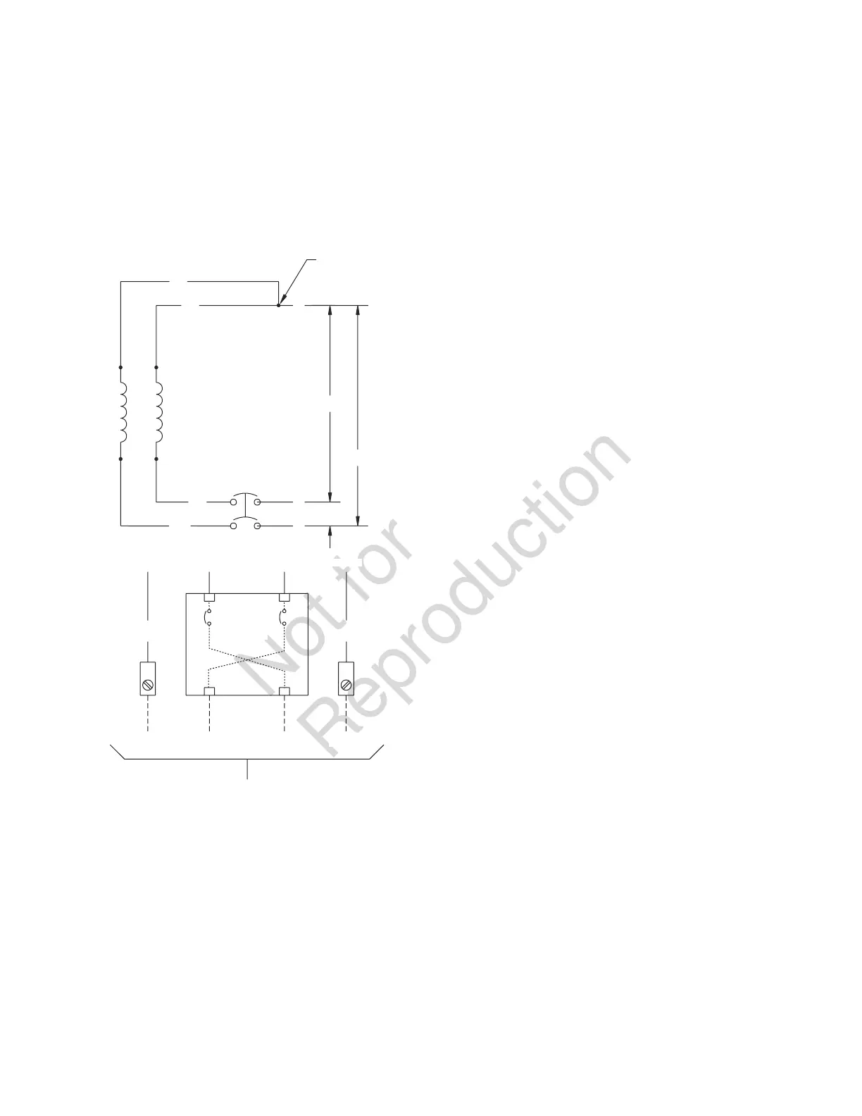
A single-phase, three-wire AC connection system is used
in the generator. The stator assembly consists of a pair
of stationary windings with two leads brought out of each
winding. The junction of leads 22 and 33 forms the neutral
lead, as shown schematically and as wiring diagram. A
complete schematic and wiring diagram can be found later in
this manual.
Neutral is not bonded to ground at generator.
NOTICE Prior to making connections, verify phase rotation
of utility power.
When making connections, obey wire type and torque
specifications shown on the circuit breaker and
neutral/ground connector.
22
120 V
120 V
240 V
44
11
33
44 11
Neutral
To Transfer Switch
Ground
Power Winding
Circuit
Breaker
Circuit
Breaker
Line 1
Neutral
Neutral
Line 2
Ground
 Loading...