Product Application Note ■ BCM5221
7/7/00 ■ BCM5220
Broadcom Corporation
5221/5220-AN01 Product Application Note, Revision R Page 20
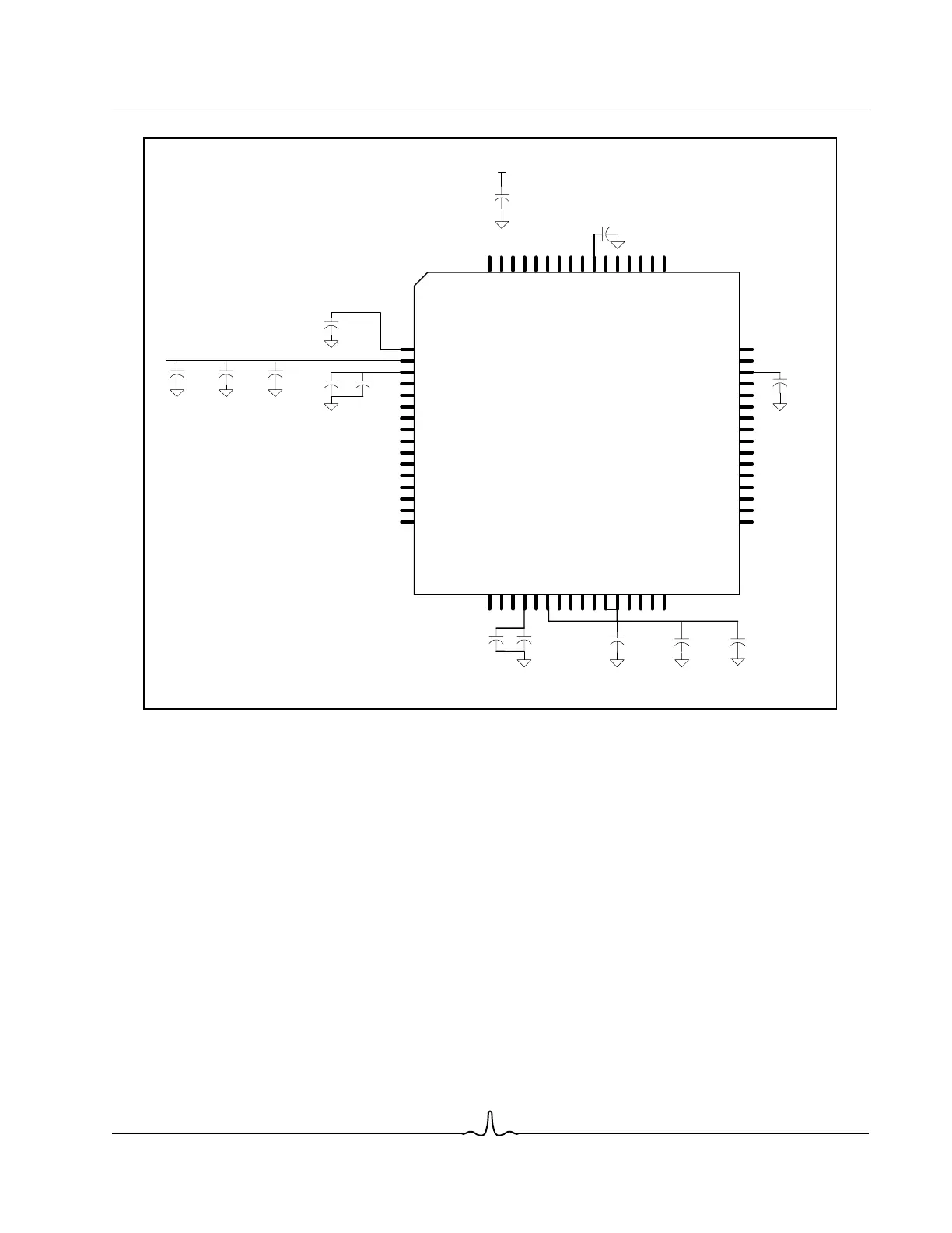
Figure 11: BCM5221 Relative Placement of Filter Components
General Layout Recommendations. The following general layout recommendations help ensure a robust overall sys-
tem design:
• Keep all trace lengths to a minimum, especially for the more sensitive signal traces between the PHY and RJ45-8.
• Each signal trace routed between the PHY and the RJ45-8 should be controlled impedance of 50Ω (100Ω differential).
• Refrain from routing traces with right-angle corners. Always chamfer trace corners as gradually as possible.
• Route differential pairs such that the + and - signals are matched in length.
• Route all MII signal traces with a target characteristic impedance of 68Ω.
• Always attempt to route noisy digital traces away from sensitive power supply pins and associated filtering such as
AVDD.
• If any two traces must cross each other, even though it would have to be on separate layers, always cross them at
90 degrees to minimize potential crosstalk.
• Always place power supply filter components as close as possible to the recommended pins (see Figure 8 on page 15)
in order to maximize the filtering effects. If a filter component cannot be directly connected to a given power pin with a
very short and fat etch, do not connect it via copper trace. Instead make the connection directly to the associated
planes with vias.
• Refrain from routing any signals (analog or digital) over non-contiguous power or ground planes as this causes interrup-
DGND
(connect to 2.5) DVDD
DGND
REGAVDD (connects to 3.3V)
BIASVDD (connect diectly to AVDD)
BIASGND
AVDD (connect to 2.5V)
AVDD (connect to 2.5V)
AGND
AGND
BCM5221
OVDD (connect to 2.5V/3.3V)
DVDD (connect to 2.5V)
REGDVDD(connect to 3.3V)
XTALGND
(connect to 2.5V/3.3V) OVDD
OGND
OGND
0.1uF
Cer 5%
1000pF
Cer 5%
0.1uF
Cer 5%
1000pF
Cer 5%
0.01uF
Cer 5%
1000pF
Cer 5%
Place a single10uF bulk
Tantalum capacitor within
an inch of the PHY as
layout will allow
10uF
Tan 20%
3.3V
1000pF
Cer 5%
0.1uF
Cer 5%
0.1uF
Cer 5%
.1uF Cer
1.0uF
Cer +80%
-20%
0.01uF
Cer
1.0uF
Cer +80%
-20%