■ BCM5221 Product Application Note
■ BCM5220 7/7/00
Broadcom Corporation
Page 19 5221/5220-AN01 Product Application Note, Revision R
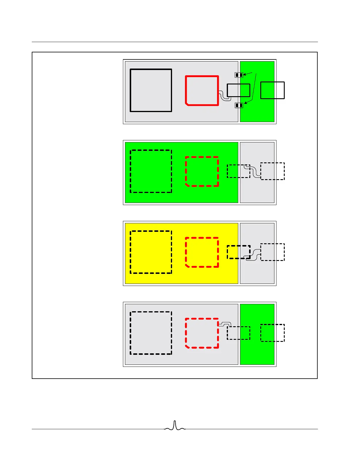
Figure 10: Typical Layer Allocation (BCM5221)
Power Supply Filter Component Placement. Power supply filter component placement is illustrated in Figure 10 and
Figure 11. Use these general placement guidelines to ensure optimal performance.
Power Plane
Mag
RJ45-8
ASIC /
MAC
Layer 1 - top
(component, signal,
and Chassis Gnd)
Layer 3
(Power & signal)
Layer 4 - bottom
(signal & chassis GND)
(components optional)
Layer 2
(Ground & signal)
Mag
RJ45-8
ASIC /
MAC
BCM5221
signal routing
Chassis
Ground
Mag
RJ45-8
ASIC /
MAC
BCM5221
Ground plane
signal
routing
BCM5221
Chassis
Ground
Mag
RJ45-8
ASIC /
MAC
BCM5221
signal routing
TX+/-
TX+/-
RX+/-
RX+/-
optional pads for
connecting chassis
to system GND
signal
routing