■ BCM5221 Product Application Note
■ BCM5220 7/7/00
Broadcom Corporation
Page 21 5221/5220-AN01 Product Application Note, Revision R
tions in the controlled impedance and results in reflections and a possible increase in EMI emissions.
• Leave the outer edges of the pcb (approximately 200 mils) voided on all layers to minimize fringe effects that could
otherwise contribute to EMI emissions.
• Other than the chassis ground area, keep the system ground plane as a single uninterrupted plane of maximum area
to create a low impedance path for all return currents. This will also help control EMI emissions.
• Connect all power and ground pins directly to their respective planes via large and/or multiple vias. Avoid routing traces
for power and ground pin connections.
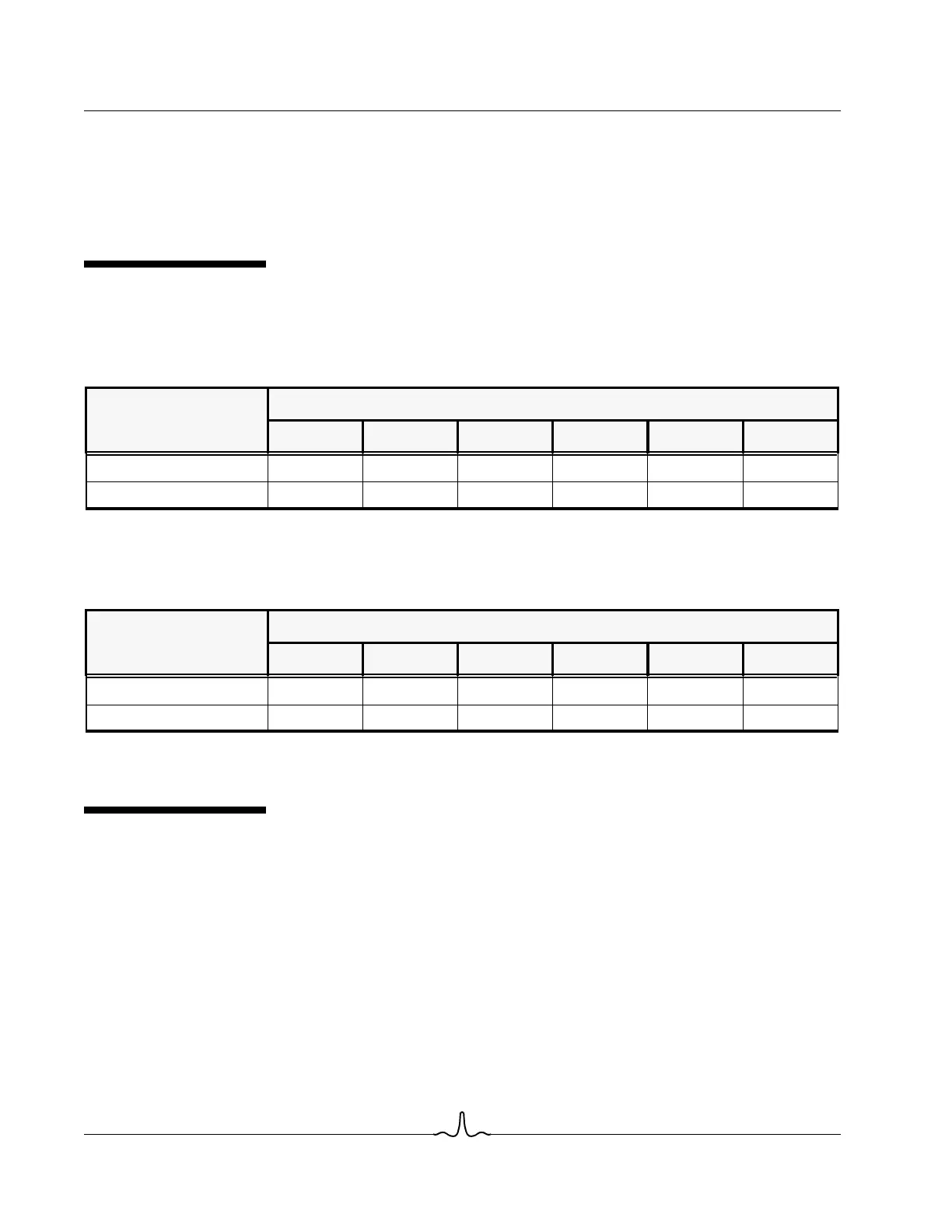
THERMAL INFORMATION
This section includes basic thermal information pertaining to the BCM522KPB and BCM5221KPT package types. Table 3
and Table 4 provide a comparison of Theta-J
A
versus Airflow.
Theta-J
C
for this package is given as 21.23 C/W. Additionally, the BCM5221KPB is designed for and rated for a maximum
Junction Temperature of 125C.
Theta-J
C
for this package is given as TBD. Additionally, the BCM5221KPT is designed for and rated for a maximum Junction
Temperature of 125C.
BCM5221 VS. BCM5220
The BCM5220 differs from the BCM5221 as follows:
• The BCM5220 does not support Auto-MDI/MDIX
• The BCM5220 does not support Cable quality Monitoring
• The BCM5220 does not provide JTAG support
Table 3: BCM5221KPB Theta-J
A
vs. Airflow
64 FPBGA Package
AIR FLOW (feet per minute)
0 100 200 400 500 600
Theta-J
A
(C/W) 35.15 25.57 22.99 20.88 20.35 20.3
Power Dissipation (W) TBD TBD TBD TBD TBD TBD
Table 4: BCM5221KPT Theta-J
A
vs. Airflow
64 PQFP Package
AIR FLOW (feet per minute)
0 100 200 400 500 600
Theta-J
A
(C/W) TBD TBD TBD TBD TBD TBD
Power Dissipation (W) TBD TBD TBD TBD TBD TBD