B102163-0-1113 Page 27
Figure 14
GRILL ASSEMBLY
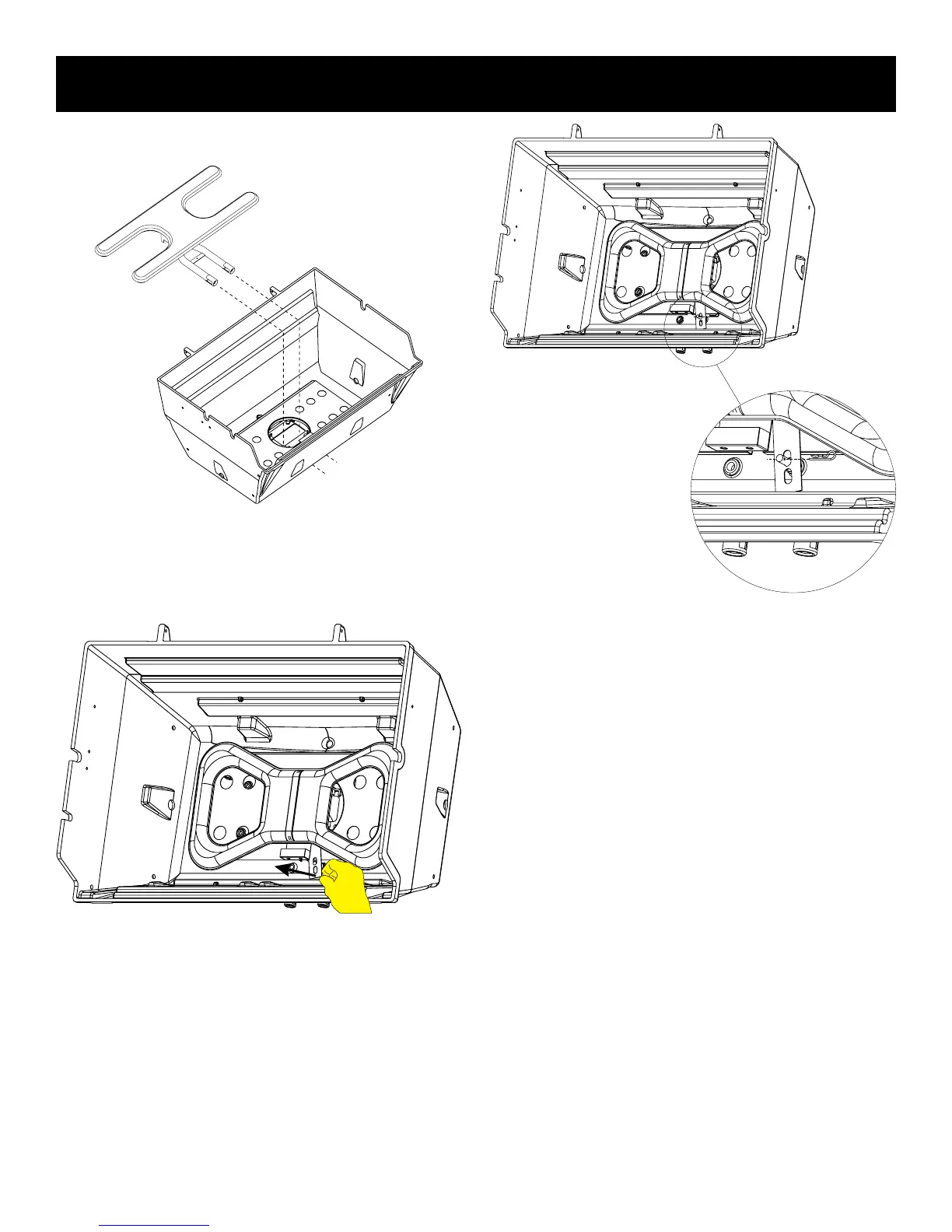
2. Insert the burner assembly into the grill bottom with the venturi
tubes facing the front of the grill. Slide venturis and ignitor wires
down through the center hole. See Figure 12.
Figure 12
3. Slide the venturi on to the valve assembly.
4. Raise the unsecured end of the burner bracket and slip it over
the 1/4-20 x 1 1/2 Phillips Truss Head Screw as shown in Figure
13. The screw will t into the hole on the burner bracket.
“P” Series Shown
Figure 13
5. Slide the bridge pin through the hole in the 1/4-20 x 1 1/2 Phil-
lips Truss Head Screw as shown in Figure 14.