B102163-0-1113Page 40
1. R3B Grills: Remove cooking grids, briquets and briquet rack
from grill.
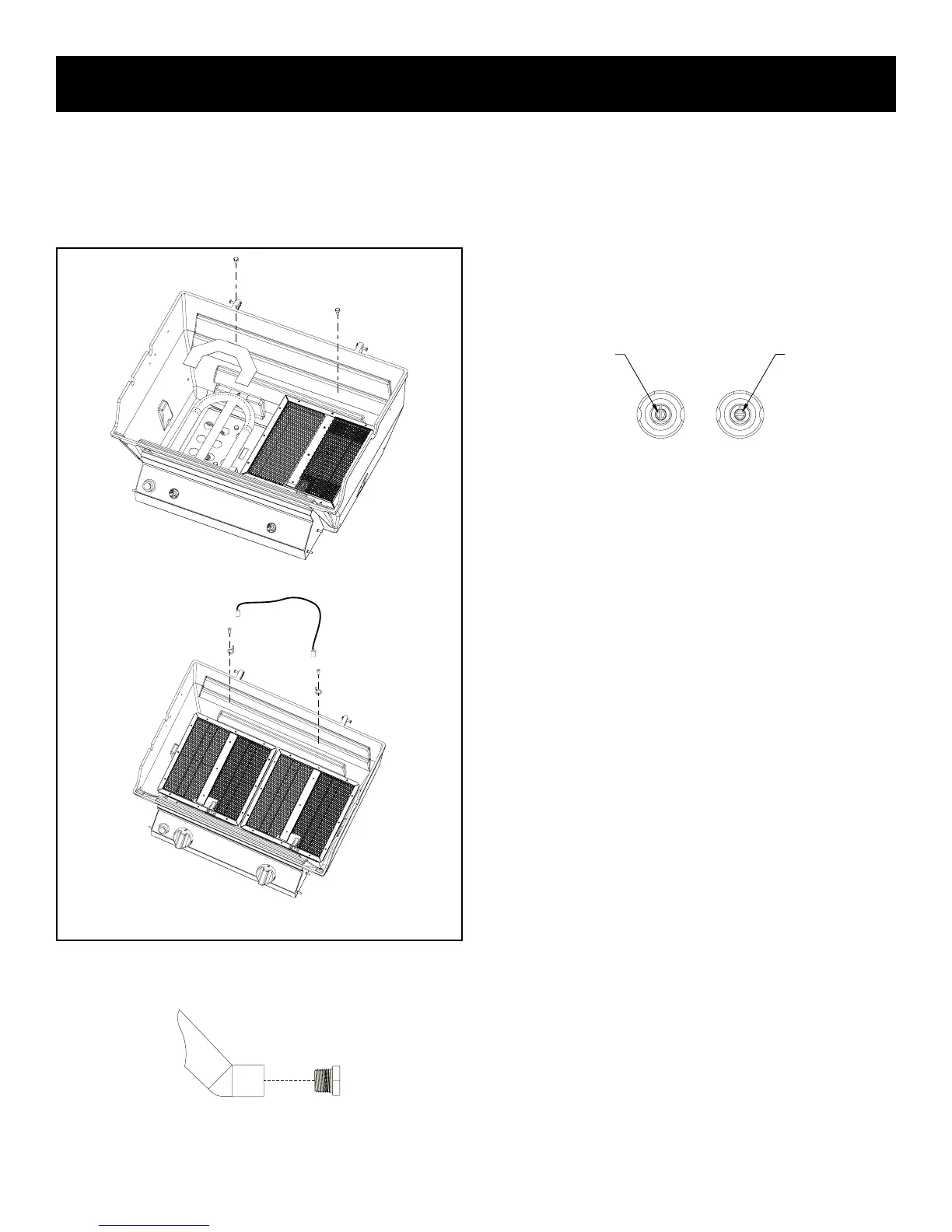
2. Blue Flame Burner: Remove blue ame burner shield and
blue ame burner from grill (one 1/4-20 x 3/4 phillips screw for
burner). See Figure 35. Infrared Burner: Remove ignitor wire,
lugs and infrared burner from grill (one 1/4-20 x 3/4 phillips
screw for each burner). See Figure 35.
R3B
R3
Figure 35
3. Remove LP burner orices marked 1.25 mm for R3B. Re-
move LP burner orice marked 1.3 mm for R3. See Figure
36.
Figure 36
4. Install natural gas burner orice marked 49 into each orice
tting. Apply pipe compound to threads on orices prior to in-
stallation.
5. Blue Flame Burner: Place burner shield and burners
into grill and insert burner tubes over orice ttings. Se-
cure each burner with one 1/4-20 x 3/4 phillips screw from
Step 2.
Infrared Burner: Place infrared burners, ignitor, and lugs into
grill and insert burner tubes over orice ttings. Secure each
burner with one 1/4-20 x 3/4 phillips screw from step 2.
6. Grasp valve knobs and remove from valves.
7. The low input adjustment screws are located inside the two
valve stems. Use a small screwdriver to turn each adjustment
screw clockwise 1/4 turn (90 degrees). When valves are in
the "OFF" position, the slot in the adjustment screw should be
vertical. See Figure 37.
LPG
NAT
ADJUSTMENT SCREW
ADJUSTMENT SCREW
Figure 37
8. Remove the hose and regulator from the gas connection on
grill with adjustable wrench.
9. Connect the grill to the natural gas supply.
Attention: Before lighting your grill check all gas con-
nections including the adjustment screws in valve stems
for gas leaks with a soapy water mixture.
Caution: Do not use the grill if a gas leak is detected until gas
leak is corrected. If a gas leak can not be stopped, do not use
grill. You must contact a qualied repair person.
10. Push valve knobs onto valves.
11. Apply the completed conversion label adjacent to the rating
plate label on the grill.
12. The natural gas inlet pressure at the grill is to be set at 7.0" of
inlet pressure.
13. Ignite burner on grill and observe ame pattern. If ame is yel-
low in color or ame is lifting off burner, the air shutter on blue
ame burners only will require adjustment.
14. Beneath the control panel you can access the air shutter
which is located on the end of the burner tube.
15. Loosen phillips screw at air shutter, open air shutter for a yel-
low ame or close air shutter for a lifting ame. Tighten phillips
screw at air shutter.
16. Ignite burners on grill to verify burner ame characteristics.
17. Replace briquet rack and briquets and reinstall cooking grids.
Installation must conform to local codes or in the absence of local
codes, with the National Fuel Gas Code, ANSI Z223.1/NFPA 54,
Natural Gas and Propane Installation Code, CSA B149.1, or Pro-
pane Storage and Handling Code, B149.2.
Caution: The grill and its individual shutoff valve must be
disconnected from the gas supply piping system during any
system pressure testing at test pressures in excess of 1/2
PSIG.
Caution: The grill must be isolated from the gas supply piping
system by closing its individual manual shutoff valve during
any pressure testing of the gas supply piping system at test
pressures equal to or less than 1/2 PSIG.
GAS CONVERSION TO NATURAL GAS