Regulations.
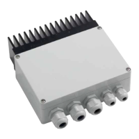
Step 1. Mount Wall Bracket/Control Housing To Wall:
UÊRemove Wall Bracket/Control Housing From
Packaging
UÊPlace the mounting bracket in position and mark
the fixing hole location on the wall. Drill holes using
appropriate drill size and type.
UÊAttach the bracket to the wall using appropriate
fixtures
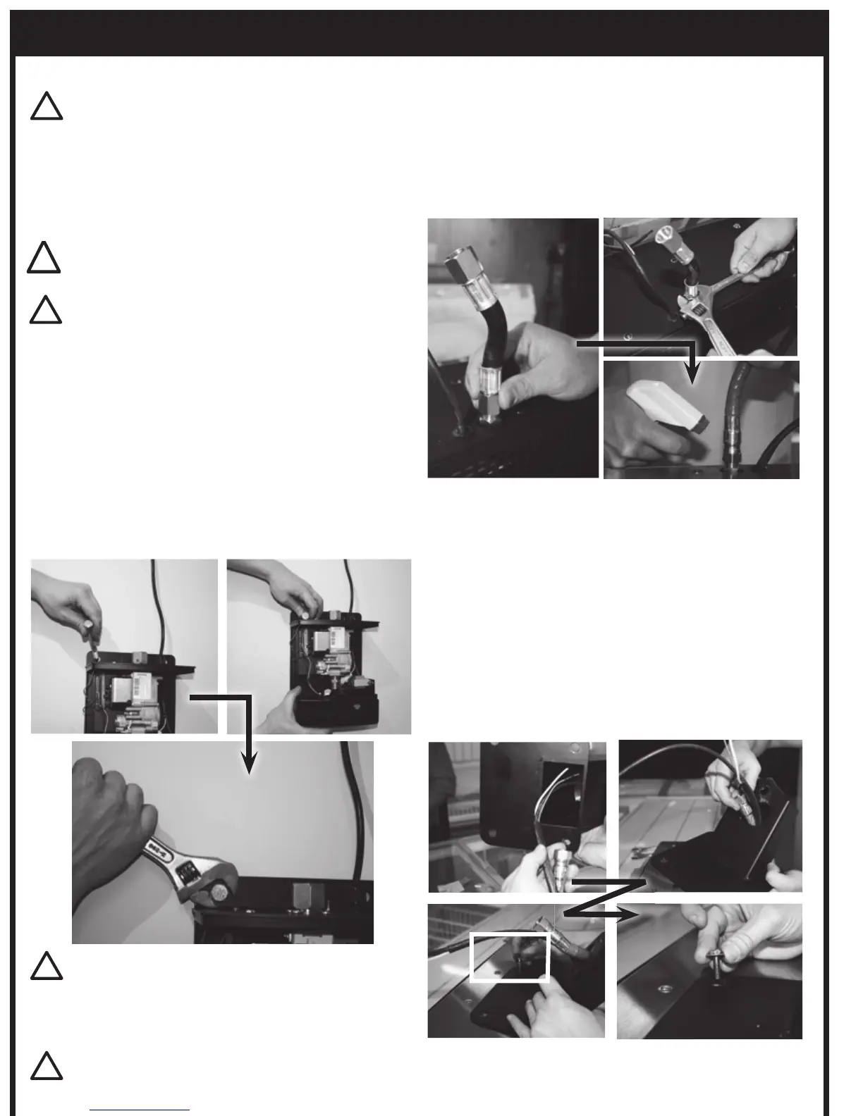
Step 2. Connect CSA approved Flexible Gas Connector
(as supplied) to the inlet fitting on the heater
using 2 wrenches to tighten. Leak Test by applying
compressed air (1/2” PSI) to open end of flexible
hose. Spray gas fittings with a soapy water solution
and Check for leaks. Alternatively, leak check can be
done after assembly using inspection hole on bracket
arm. (see. leakage test section of this manual).
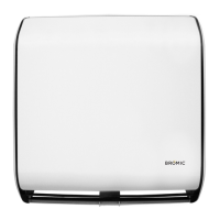
Step 3. Fix Mounting Arm to the back of the heater –
UÊSlide Gas Connector and Wiring Harness inside the
centre of the arm and have them exit through the
shaped cut-out on top surface of the arm
UÊEnsure that the arm faces downwards at a 55º angle
UÊPosition the 4 mounting holes on the arms plate
over the corresponding fixtures on the heater -
Manipulate the gas hose as necessary to allow for
correct alignment
UÊInsert and tighten 4 M6 bolts as provided to fit
mounting arm to heater.
WARNING
When mounting wall bracket/ control housing, ensure the
anchoring to the structure is of sufficient strength, quality
and workmanship to support the weight of the heater and
IMPORTANT
The Heater shall be firmly and securely attached to the wall.
For Brick and masonry, use M8 “Flush Head” “Dynabolts”
(or equivalent). For Wood / Timber fixtures, use suitable
screw fixings no less than 60mm in length.
WARNING
This appliance must be installed and used in accordance
with local codes, or in the absence of local codes, with the
National Fuel Gas Code, ANSI Z223.1/NFPA 54, Natural Gas
and Propane Installation Code, CSA B149.1, or Propane
Storage and Handling Code, B149.2 and must meet all the
requirements stipulated in the “Installation Requirements”
section of this manual.