Page 18 EL-FLOW Base Series Mass Flow Controllers 9.17.061
A special RS232 cable (7.03.366) can be ordered separately. It consists of a T-part with 1 male and 1
female sub-D 9 connector on one instrument-side and a normal female sub-D 9 connector on the side of
the computer. By means of this cable it is possible to offer RS232 communication and still be able to
connect power-supply and analog interface through the (analog) sub-D 9 connector.
3.5 Modbus RS485 operation
This chapter is limited to the description of the interface between the Modbus Mass Flow Controller
with a master device. It will explain how to install an EL-FLOW Base instrument to your Modbus system.
It only contains the information that is needed most.
The implementation of the Modbus interface is based on the following standards:
[1] MODBUS Application Protocol Specification V1.1b, December 28, 2006
[2] MODBUS over Serial Line specification and implementation guide V1.02
There is no mutual communication between Modbus slaves; only between master and slave.
More detailed information about Modbus can be found at http://www.modbus.org or any website of
the (local) Modbus organisation of your country (when available).
Physical layer and communication protocol are detected automatically upon reception of messages.
These messages must be sent using the correct combination of physical layer and communication
protocol. After every power-up the communication detection mode is active.
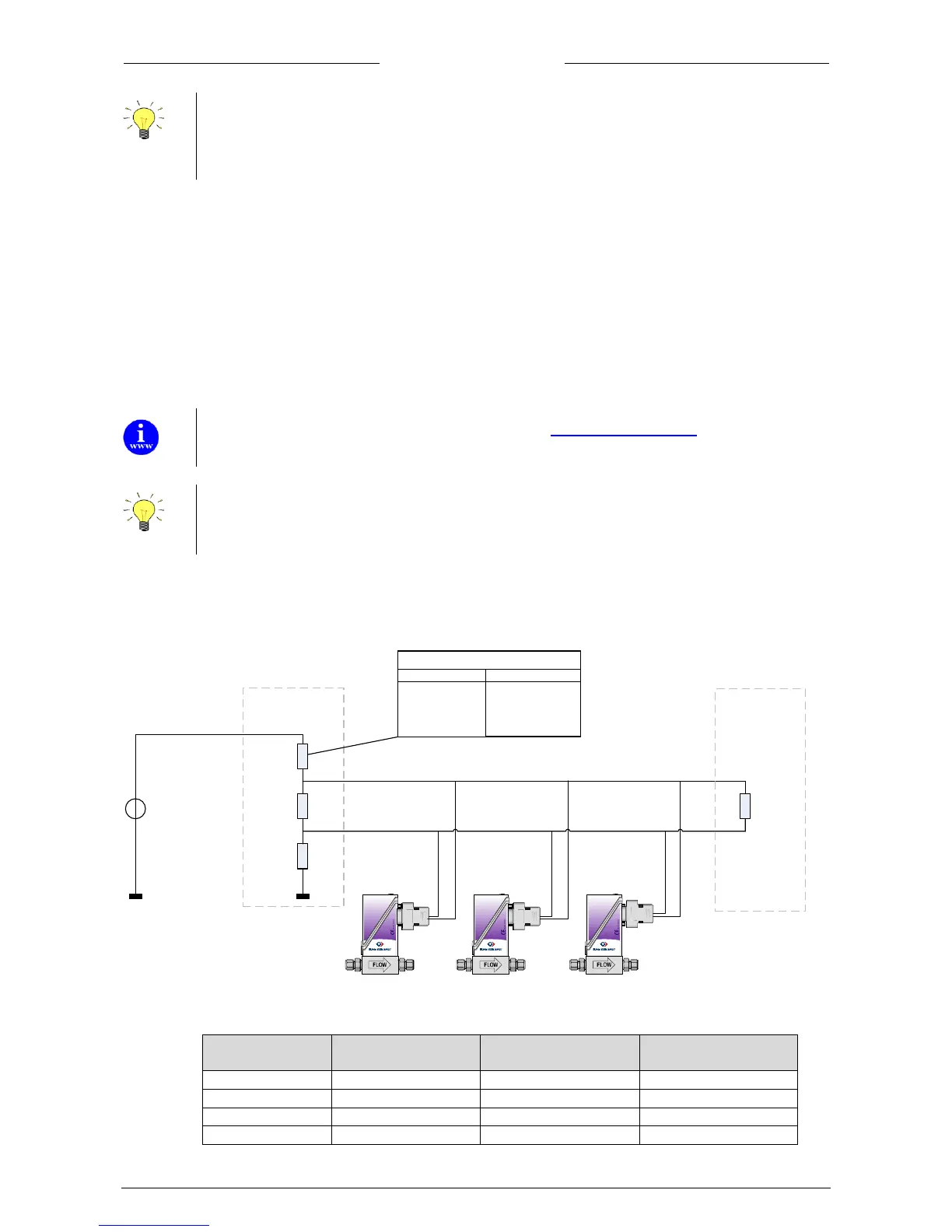
3.5.1 Modbus termination
The Modbus must be terminated correctly with termination resistors (RT1, RT2) and biasing resistors
(RB1, RB2).
EL-FLOW
®
Base
mass flow meter/controller
EL-FLOW
®
Base
mass flow meter/controller
EL-FLOW
®
Base
mass flow meter/controller
D1 Modbus (B/B’)
D0 Modbus (A/A’)
+
-
RT1
121 Ohm
RB2
392 Ohm
RB1
End termination
Begin termination
Supply Voltage
Remark: See hookup diagram for details
RB1 value depends on supply voltage
Supply Voltage RB1
+5V 392 Ohm
+10V 1210 Ohm
+15V 2210 Ohm
+24V 3480 Ohm
RT2
121 Ohm
Bronkhorst® advices the following resistor values for the following voltages:
Supply voltage
termination
Bias Pull-up resistor
RB1
Termination resistor
RT1 & RT2
Bias Pull-down resistor
RB2