Do you have a question about the Brooks ATR60LF and is the answer not in the manual?
ATR60LF READER CAN Bus. Details serial number, part number, and manufacturer information.
Specifies product use for reading/writing transponders in industrial settings only.
Details compliance with FCC Part 15 rules, device may not cause harmful interference.
Declaration of Conformity for the European Union, listing product standards and directives.
Covers warranty period, conditions, and exclusions for damages and property loss.
Explains purpose of instructions: safety, transport, installation, operation support.
Defines safety symbols (DANGER, WARNING, CAUTION, ATTENTION, IMPORTANT) and their meanings.
Describes device construction, intended use, and general safety symbols.
Details specific warning symbols like hazardous area, electrical voltage, and flammable materials.
Lists symbols for prohibited actions such as unauthorized access and switching.
Explains symbols for disposal, recycling, and referring to the manual.
Outlines company responsibilities for safe operation, trained personnel, and reporting safety deficiencies.
Details personnel duties for preventing accidents and the consequences of insufficient qualifications.
Describes the RFID reader system as a radio-frequency identification system.
Lists core functions: reading/writing data, setting parameters, subsystem commands, and read status.
Explains reader operation after reset and power-up events without independent actions.
Details the 'Automatic Reading' option triggered by sensors with defined delay times.
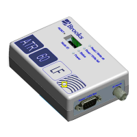
Illustrates the front of the device, labeling RS232 and Remote I/O ports.
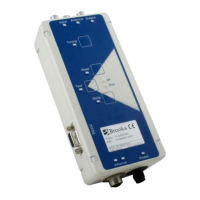
Shows the rear of the device, labeling Power/CAN Bus connection and Antenna port.
Details the top view, identifying the Reset button, DIP switches, and Status LEDs.
Describes the device label containing CE mark, part number, and serial number.
Details voltage and current requirements for the device, including pulsed and passive current.
Lists safety precautions for installation, including indoor use, temperature, humidity, and water avoidance.
Emphasizes that installation must be performed by specially trained personnel only.
Instructs on unpacking procedures, maintaining clean-room conditions, and disposing of packaging material.
Details mounting surface requirements and device installation for proper air circulation.
Explains how transponder distance and orientation affect reading/writing and recommends antenna tuning.
Mentions that different types of antennas are available upon request.
Guides on connecting the antenna, power supply, and CAN Gateway.
Details the DC power connection, LED indicators, and pin assignments for the Power/CAN bus connector.
Describes the RS232 port as an RJ45 socket and its pin assignments for PC connection.
Lists prerequisites for reader operation: antenna, power supply, transponder, and gateway connection.
Specifies baud rate, data bits, stop bit, and parity for serial communication.
Defines CAN Bus interface speed (kBits/sec) and message length.
Details the Remote I/O port for sensors and outputs, including pin assignments and connection examples.
Explains how DIP switches set TargetID, test mode, and activate antenna tuning.
Illustrates the network configuration for the AdvanTag CAN Bus, showing connections between components.
States that the reader is for specially trained personnel and warns about unqualified operation.
Explains communication between ATR60LF Reader and CAN Gateway via CAN Bus Port.
Defines ATTRID for attributes and ATTRVAL for attribute values, used for configuration and status.
Defines Group Event Report IDs for events like material arrival/removal and power-up.
Specifies command parameters like LED status, LED number, operation status, page number, and timeout.
Details reading/writing data for foup transponders, single or multi-page IDs.
Defines DATALENGTH for total bytes and DATASEG for data source/offset for reading/writing.
Provides equipment model number and software revision code.
Defines message header structure and SSACK acknowledge codes for errors and normal operation.
Details subsystem commands like LED control, self-test, reset, and status change.
Describes status of UP-STREAM CONTROLLER and associated NODEs.
Defines current status values for CIDRW and Head, including PM information and alarm status.
Explains TargetID for subsystem identification, set via DIP switches.
Provides read-only alarm status and inter-byte timeout settings.
Configures inter-block timeout and communication baud rate.
Sets carrier ID length/offset, checksum, and CID display options.
Covers CID padding, error handling, justification, max length, non-printable characters, and zero padding.
Details device configuration, ID, and type (CIDRW).
Explains the dual sensor mode for triggering automatic reads and its behavior.
Controls enabling of events and communication timeouts.
Enables extended error codes in SSACK for detailed fault reporting.
Covers hardware revision, head ID, status, host LED control, and network hostname.
Enables writing MID/CID according to E99 standard for maintenance.
Specifies manufacturer and model number details.
Defines operational status (IDLE/MANT) and serial port parity settings.
Configures PIP sensor status, auto-read, and data memory type.
Sets PIP auto-read length and sensor polarity.
Configures radio retries, RDA response, manual antenna adjustment, and repeat time.
Indicates the result of the last self-test.
Configures sensor delay and provides serial number information.
Details signal strength, software revision, and revision level.
Manages status communication, TargetID, and DIP switch usage for testing.
Explains SECS-I standard for messaging between equipment and host, covering its layers and limitations.
Describes SECS-I reader-host communication via RS232, character structure, and master-slave roles.
Defines handshake codes (<ENQ>, <EOT>, <ACK>, <NAK>) and SECS message block format.
Explains HSMS protocol for Ethernet interface, acting as a server waiting for host connection inquiries.
Details HSMS connection status, including NOT CONNECTED, CONNECTED (NOT SELECTED, SELECTED).
Describes the 'SELECTED' state in HSMS, enabling data message exchange, and lists connection state transitions.
Outlines procedures for HSMS connection, select, data exchange, and termination.
Defines the structure of HSMS messages: length, header, and message text.
Breaks down the 10-byte HSMS header: Session ID, P-type, S-type, and System bytes.
Provides a summary table of HSMS message types, bytes, and their roles.
Defines SECS-II message structure, categories (streams/functions), items, and lists.
Lists SECS-II data item formats: List, Boolean, Binary, ASCII, Integers, Floating Point.
Outlines the SECS-II message set used, including stream types for equipment status and system errors.
Explains SEMI E99 for Carrier ID reader/writer, covering purpose, scope, and status models.
Defines the status states of the BROOKS RFID reader, such as IDLE, BUSY, ALARMS, OPERATING.
Details the state transitions of the BROOKS SECS-I status model based on triggers and actions.
Provides general guidance for servicing, emphasizing Brooks-only service and contacting support for uncertainties.
Stresses that error handling must be done by trained personnel and to contact Brooks if uncertain.
Highlights safety precautions for troubleshooting, including high voltages, spare parts, and fuses.
Lists SSACK codes (NO, EE, CE, HE) with descriptions, causes, and correcting actions for errors.
Details stream function errors like unrecognized DeviceID, stream type, function type, illegal data, and timeouts.
Explains LED indicators for power status and read/write failures, and troubleshooting steps.
Provides troubleshooting steps when the reader is unresponsive, checking cables and LEDs.
Describes hardware reset by power cycling and self-test behavior after power cuts.
Lists software release history and provides contact information for technical support.
Outlines steps for dismantling the device: removing power, cables, and mounting screws.
Provides instructions for storing the reader and components in a clean, dry environment.
Details how to package the device securely in a cardboard box with padding for transportation.
Instructs on proper disposal of electronic components, antennas, cables, and casing as waste.
| Operating Temperature | -20°C to +55°C |
|---|---|
| Polarization | Circular |
| IP Rating | IP65 |
| Weight | 2.5 kg |
| Protocol | ISO 18000-6C |
| Interface | Ethernet |