
S
Sean MortonSep 7, 2025
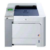
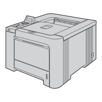
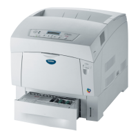
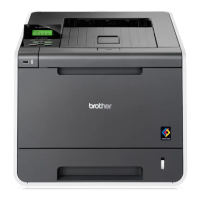
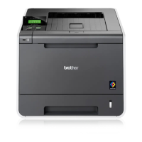
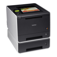
What to do if my Brother HL-4040CN, HL-4050CDN, HL-4070CDW has a 'Color registration sensor failure'?
- RRobert BrownSep 7, 2025
If your Brother printer is showing a 'Color registration sensor failure', turn the power off and then back on again.