C
Christopher BryantSep 3, 2025
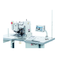
What to do if Brother KE-434B does not operate when turned on?
- DDustin HollandSep 3, 2025
If the machine does not operate when the power is turned on and the foot switch is depressed: * Check if the head position switch cord is disconnected. * Adjust the position of the switching plate. * Replace the head position switch if it is broken.