3-73
Confidential
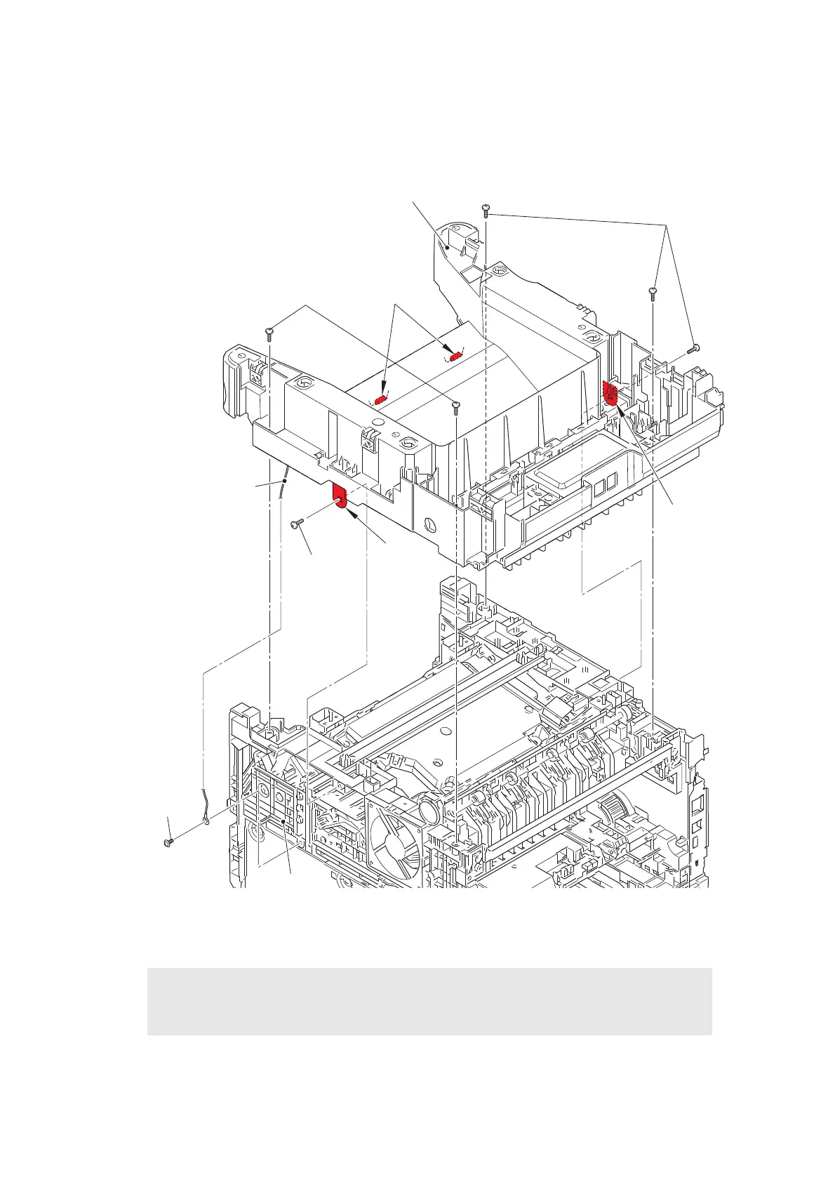
(2) Remove the taptite cup S M3x8 SR screw to remove the modem FG harness R.
Release the modem FG harness R from the securing fixtures of the hold cover 1.
(3) Remove the six taptite bind B M4x12 screws. Release each hook to remove the joint
cover ASSY.
Fig. 3-71
Harness routing: Refer to “9. Speaker unit, Modem (LVPS side)”.
Assembling Note:
• When assembling the joint cover ASSY, be careful not to damage the wireless LAN
PCB.
Hook
Taptite bind
B M4x12
Taptite bind
B M4x12
Taptite bind B M4x12
Hooks
Hook
Joint cover ASSY
Modem FG harness R
Taptite cup
S M3x8 SR
Hold cover 1
 Loading...