7-5
Confidential
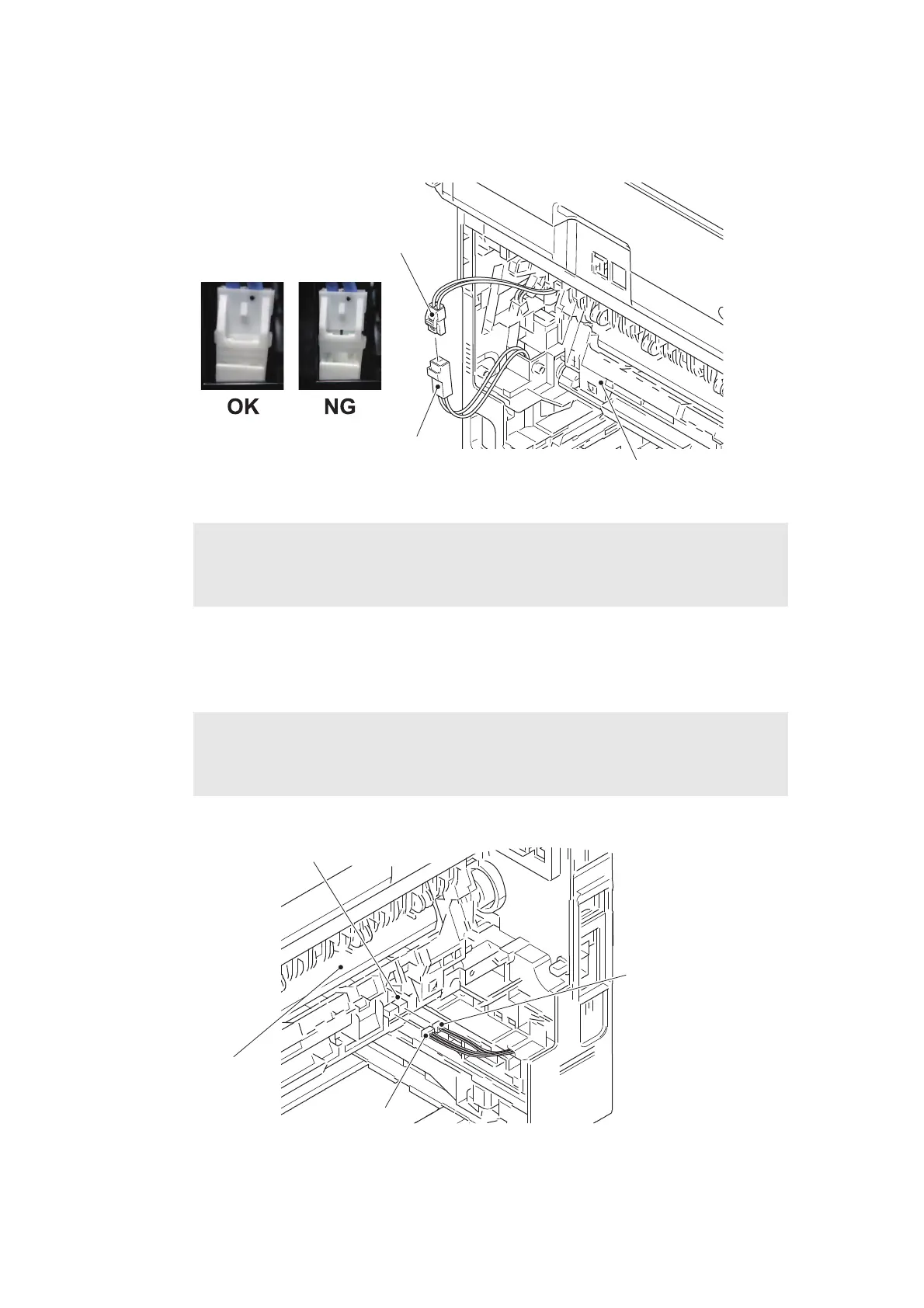
(11) Release the heater harness of the fuser unit from the securing fixtures, and disconnect it
from the low-voltage heater harness.
Fig. 7-6
Harness routing: Refer to “11. Rear side of the machine”.
(12) Disconnect the center thermistor harness and the side thermistor harness from the eject
sensor PCB ASSY.
Fig. 7-7
Harness routing: Refer to “11. Rear side of the machine”.
Assembling Note:
• After connecting the heater harness, pull the connector on the heater harness side while
holding the connector on the low-voltage heater harness side to make sure it is locked.
Note:
• When disconnecting the harness, hold the top of the PCB connector to prevent the
PCB connector being damaged.
<Frame R side>
Heater harness
Fuser unit
Low-voltage heater harness
Center thermistor
harness
Eject sensor PCB ASSY
Side thermistor
harness
Fuser unit
<Frame L side>
 Loading...