PG.
PROGRAMMING BOOLEAN FUNCTIONS (See Menus 45, 46, 47)
Brovind controllers can be used to program logic functions which control the board inputs (sensors) and
outputs (actuators).
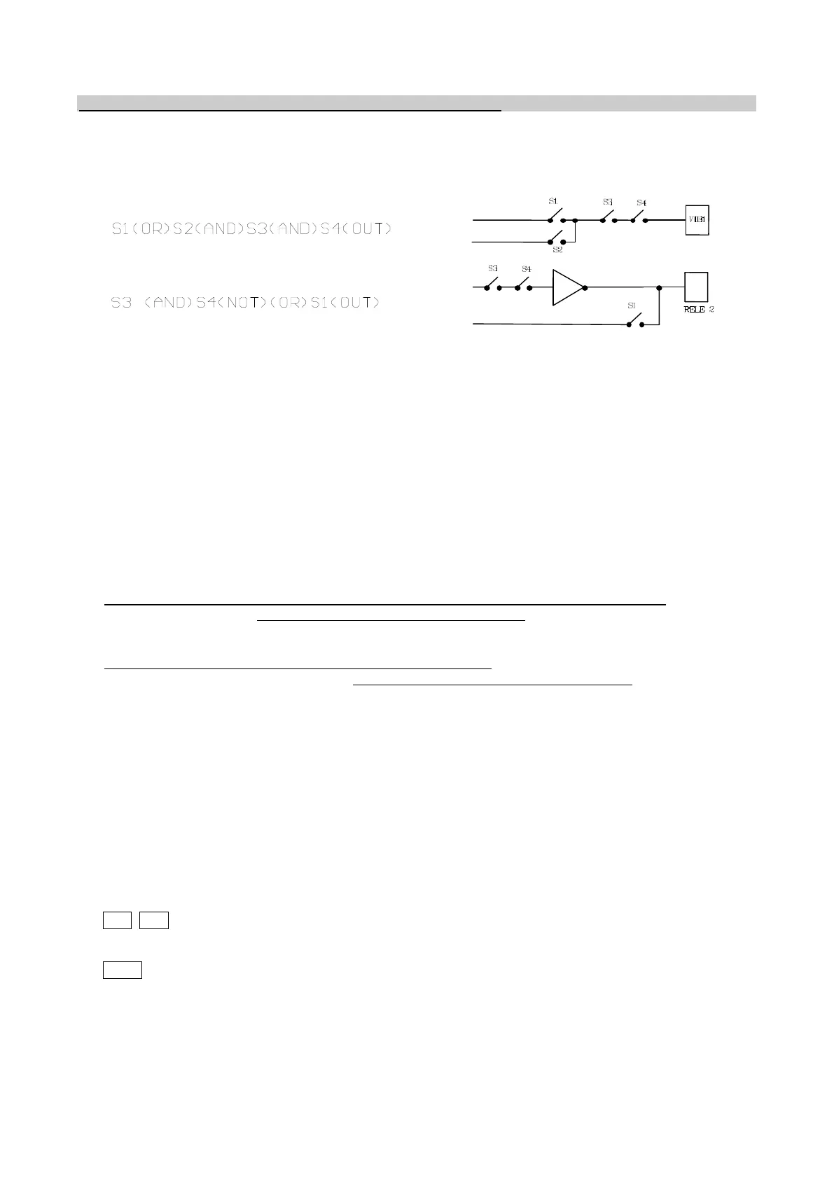
For example:
The resources available for the program generation are (the ones with “*” only from the ver. 4.00 onwards):
- Max. number of blocks: 12 (6 for the software versions preceding the 4.00 of all the models)
- Max. number of inputs (sensors) available on DCFF*: 6 (S1, S2, S3, S4, S5, S6)
- Max. number of inputs (sensors) available on CFV and CFF: 3 (S1, S2, S3)
- “Virtual” inputs (pieces-counter function) on all boards*: 2 (c1, c2)
- Max. number of outputs (actuators) available on DCFF: 5 (Vib1, Vib2, Rel1, Rel2, Rel3)
- Max. number of outputs (actuators) available on CFV and CFF: 2 (Vib1, Rel1)
- “Virtual” outputs available on DCFF: 6 (1.1A, 1.2A, 1.3A, 2.1A, 2.2A, 2.3A)
- “Virtual” outputs available on CFF and CFV: 3 (1.1A, 1.2A, 1.3A)
- Memories (inputs/outputs) on all boards*: 2 (M1, M2)
- Max number of Timer available on DCFF 2(T1; T2)
- Max. number of elementary functions on all boards*: 6 (AND, OR, NOT, OUT, SET, RST)
- Max. number of elements which can be inserted in a block: 16 (selected by user from inputs-
outputs or elementary functions)
NOTES for using functions (Menus 45, 46, 47)
- The sensors inserted in each program block are first enabled in the assigned menus.
- The inputs S5 (DCFF1), S6 (DCFF2 from the version 5.00 onwards) or S3 (CFF and CFV) are 0-10 V
used logically (0 logic or 1 logic): to use them first enable them (Menu 8) and then state their use in Menu
46.
- For DCFF boards with the software version preceding the 5.00 if the input 0-10 V is enabled on board
DCFF2 it will only work in analog mode: in any case S5, in Menu 46 must be disabled.
- If an uncoded function has been inserted in the block (e.g. “---“) it is considered a null function.
- If an uncoded input has been inserted in the block (e.g. “---“) the block result will be “0” logic.
- If outputs Rel1 and Rel2 (DCFF only) are not used in the user-defined blocks, they continue to work as
status relays.
- The program also works if the Master is connected since it generates and transmits the actuator
condition which is subsequently modified by the program.
- When blocks are created and the results of a series of logical operations are assigned to an output
(actuator), the following should be noted:
- 1) The control logic of outputs Vib1 and Vib2 is denied, i.e. if the block result is “1” then Vibrator 1 or
Vibrator 2 are OFF.
2) The control logic of outputs Rel1, Rel2 and Rel3 is direct, i.e. if the block result is “1” then Relay 1 or
Relay 2 or Relay 3 are ON.
- When the default (Menu 30) or user configuration (Menu 41) parameters are reset, the following should
be noted:
CFF CFV
The program is disabled if you decide to reset the default parameters on the board
The program is disabled if you decide to reset a board user configuration with RelayMode which is not 0.
DCFF
The program is disabled if you decide to reset the default parameters on the DCFF1 board.
The program is not disabled if you decide to reset the default parameters on the DCFF2 board but they
must be re-enabled if its sensors (S3 and/or S4) have been used.
The program is disabled if you decide to reset a DCFF1 or DCFF2 user configuration with RelayMode
which is not 0.
ATTENTION: If you encounter problems when compiling and generating the program, contact the Supplier.