BR3000-330-2CL,-3CL,-2EN CMM and IPL
Document No. 33-21-57, Rev. A
Page 50
5.9.1.2.1 LCM Input Current Measurement
Measurement of the input current of a single LCM unit during the HIGH (Default White)
mode of operation can provide a quick confidence check of proper LCM circuit operation
if a partial fault is suspected.
1. With the LCM unit under test configured as shown in Figure 20 apply 115 +/- 2
Vac, 400Hz power to the LCM. Do not apply 28 Vdc power to the MLCP at this
time.
2. After 3 seconds, the LCM unit should automatically transition to the HIGH
(Default White) mode of operation which represents the maximum power
consumption mode for the LCM.
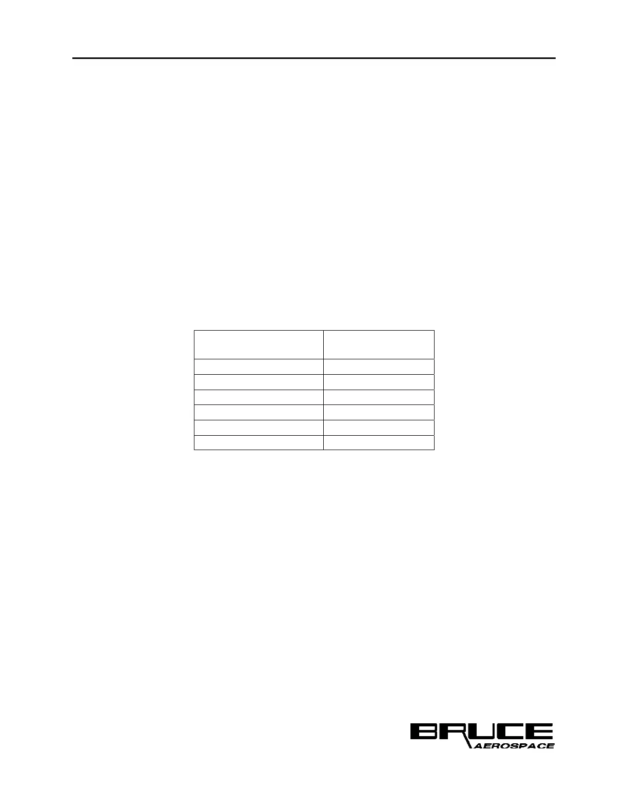
3. Measure the input current for the LCM unit. The current measurement should
correspond to the values provided in Table 7.
Table 7 BR2900 LCM Input Current Test Parameters
BR3000 LCM Unit
Input Current,
HIGH Scenario
BC1-0229-001 .171-.209 A
BC1-0229-002 .171-.209 A
BC1-0229-003 .171-.209 A
BC1-0230-001 .270-.330 A
BC1-0230-002 .270-.330 A
BC1-0230-003 .270-.330 A
5.9.1.2.2 LCM On/Off Control Test
1. With the LCM unit under test configured as shown in Figure 20 apply 115 +/- 2
Vac, 400Hz power to the LCM.
2.
Apply 28 Vdc power to the MLCP unit. It should initialize in the Day Mode of
operation, with the High Scenario selected.
3. Verify that the LCM On/Off control switch is in the ON (open) position.
4. The LCM unit should transition to the HIGH (Default White) mode of operation.
5. Place the LCM On/Off control switch in the OFF (closed) position. The LCM unit
under test should immediately extinguish.
6. Place the LCM On/Off control switch back in the ON (open) position. The LCM
unit under test should rapidly transition back to the HIGH (Default White)
presentation.
 Loading...